Modeling of IO System Using E2E Techniques: Insights from SIMLIGO
This study explores the modeling of the Input-Output (IO) systems used in gravitational wave detection, specifically focusing on the end-to-end (E2E) modeling techniques applied within the SimLIGO framework. Key aspects of the modeling include the HAM table with suspension boxes, vibration isolation, and the dynamic interactions between various components. The analysis incorporates data from accelerometers to estimate table motion and optimize local damping for mode cleaners. Preliminary results indicate the efficacy of the combined MC and IFO systems in improving the overall performance of gravitational wave detectors.

Modeling of IO System Using E2E Techniques: Insights from SIMLIGO
E N D
Presentation Transcript
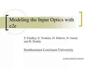
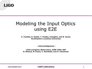
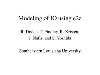
Modeling of IO using e2e R. Dodda, T. Findley, R. Kristen, J. Nafis, and S. Yoshida Southeastern Louisiana University
Acknowledgment • LIGO Livingston Observatory • SURF 2004 • NSF • B. Bhawal, M. Evans, V. Sannibale, H. Yamamoto,
Outline • Modeling HAM table with suspension box • SOS box and DAQ • MC box • Combine with IFO box (SimLIGO)
Suspension Point Tower Wire OSEM Sensors HAM table Vibration isolation stacks Accelerometer òò = x ( t ) ACCX dt dt HAM and accelerometer on cross beam Table motion estimation
Make cross-beam displacement HAM1 v(t) HAM1 a(t) HAM1 x(t) HAM2 x(t)
òò ACCX dt dt u v ¶ ¶ 1 1 - = - Table yaw = ( ) { ik u ( y , t ) ik v ( x , t )} 1 2 ¶ ¶ 2 y x 2 w ± w ± ( ) ( ) i t k y i t k x = = u ( y , t ) A e , v ( x , t ) A e 1 1 2 2 0 0 = = w q = w - k k k ( ) i k ( ){ u ( y , t ) v ( x , t )} 1 2 Modeling HAM table motion Model HAM table motion X in Table u HAM stack box Table v Y in
òò = w = F x ( t ) ACCX dt dt X ( ) { x ( t )} Cross beam displacement input Cross - beam displacement used for MC1_w_HAM.box
MC1 box HAM box
MMT1 Mode Matching Telescope MMT2 MC3 MMT3 ModeCleaner MC1 HAM1 HAM2 FromPSL Input Optics To IFO MC2 HAM: Horizontally Accessible Module
SM (0.75, 0.45) V MMT1 (0.1, 0.4) MC3 (0.75, -0.05) U q (0, 0) MMT3 (-0.8, 0.6) MC1 (0.75, -0.25) Suspension point motion of each optic U: table’s center of mass translational motion V: table’s center of mass translational motion q: table’s yaw motion u(x,y)=U - yq v(x,y)=V + xq
Conclusions • HAM table motion estimated from ACC DAQ signal • MC1 – MC3 local damping optimized • MC box constructed and being tested • Combination of MC and IFO in progress