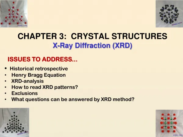
X-ray Diffraction (XRD)
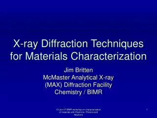
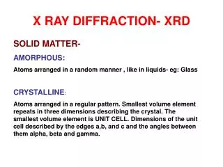
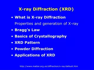
X-ray Diffraction (XRD). What is X-ray Diffraction Properties and generation of X-ray Bragg’s Law Basics of Crystallography XRD Pattern Powder Diffraction Applications of XRD . X-ray and X-ray Diffraction.

X-ray Diffraction (XRD)
E N D
Presentation Transcript
X-ray Diffraction (XRD) • What is X-ray Diffraction Properties and generation of X-ray • Bragg’s Law • Basics of Crystallography • XRD Pattern • Powder Diffraction • Applications of XRD
X-ray and X-ray Diffraction X-ray was first discovered by W. C. Roentgen in 1895. Diffraction of X-ray was discovered by W.H. Bragg and W.L. Bragg in 1912 Bragg’s law:n=2dsin Photograph of the hand of an old man using X-ray.
Properties and Generation of X-ray • X-rays are electromagneticradiation with very short wavelength ( 10-8 -10-12 m) • The energy of the x-ray can be calculated with the equation E = h = hc/ • e.g. the x-ray photon with wavelength 1Å has energy 12.5 keV
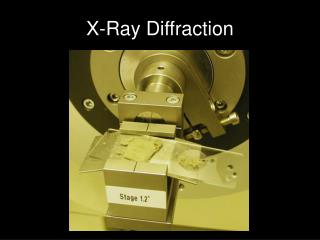
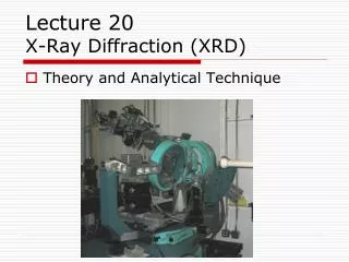
A Modern Automated X-ray Diffractometer X-ray Tube Detector Sample stage Cost: $560K to 1.6M
Production of X-rays Cross section of sealed-off filament X-ray tube W target X-rays Vacuum X-rays are produced whenever high-speed electrons collide with a metal target. A source of electrons – hot W filament, a high accelerating voltage (30-50kV) between the cathode (W) and the anode and a metal target. The anode is a water-cooled block of Cu containing desired target metal.
X-ray Spectrum • A spectrum of x-ray is produced as a result of the interaction between the incoming electrons and the inner shell electrons of the target element. • Two components of the spectrum can be identified, namely, thecontinuous spectrum and thecharacteristic spectrum. I Mo k characteristic radiation continuous radiation k SWL - short-wavelength limit
Short-wavelength Limit • The short-wavelength limit (SWL or SWL) corresponds to those x-ray photons generated when an incoming electron yield all its energy in one impact. V – applied voltage
The Continuous x-ray Spectra • The electrons enter the target with kinetic energy equals to eV, where V is the accelerating voltage used. • Fast moving e- will then be deflected or decelerated and EMradiation will be emitted. • The energy of the radiation depends on the severity of the deceleration, which is more or less random, and thus has a continuous distribution. • These radiation is called white radiation or bremsstrahlung (German wordfor ‘braking radiation’). Any decelerated charge emits energy KE=eV=½(mv2)
Characteristic x-ray Spectra • Sharp peaks in the spectrum can be seen if the accelerating voltage is high (e.g. 25 kV for molybdenum target). • These peaks fall into sets which are given the names, K, L, M…. lines with increasing wavelength. Mo
Characteristic x-ray Spectra L K K2 K1 • If an incoming electron has sufficient kinetic energy for knocking out an electron of the K shell (the inner-most shell), it may excite the atom to an high-energy state (K state). • One of the outer electron falls into the K-shell vacancy, emitting the excess energy as a x-ray photon. K I II III K L M L K state Energy K K L state L M state N state ground state
Characteristic X-ray Lines K K and K2 will cause Extra peaks in XRD pattern, but can be eliminated by adding filters. -----is the mass absorption coefficient of Zr. I K1 <0.001Å K2 K =2dsin (Å) Spectrum of Mo at 35kV
Absorption of x-ray • All x-rays are absorbed to some extent in passing through matter due to electron ejection or scattering. • The absorption follows the equation where I is the transmitted intensity; I0 is the incident intensity x is the thickness of the matter; • is the linear absorption coefficient • (element dependent); is the density of the matter; (/) is the mass absorption coefficient (cm2/gm). I0 I I , x x
Effect of , / (Z) and t on Intensity of Diffracted X-ray incident beam crystal diffracted beam film
Absorption of x-ray • The mass absorption coefficient is also wavelength dependent. • Discontinuities or “Absorption edges” can be seen on the absorption coefficient vs. wavelength plot. • These absorption edges mark the point on the wavelength scale where the x-rays possess sufficient energy to eject an electron from one of the shells. / Absorption coefficients of Pb, showing K and L absorption edges.
Filtering of X-ray • The absorption behavior of x-ray by matter can be used as a means for producing quasi- monochromatic x-ray which is essential for XRD experiments. • The rule: “Choose for the filter an element whose K absorption edge is just to the short-wavelength side of the K line of the target material.”
Filtering of X-ray K absorption edge of Ni • A common example is the use of nickel to cut down the K peak in the copper x-ray spectrum. • The thickness of the filter to achieve the desired intensity ratio of the peaks can be calculated with the absorption equation shown in the last section. No filter Ni filter Comparison of the spectra of Cu radiation (a) before and (b) after passage through a Ni filter. The dashed line is the mass absorption coefficient of Ni.
Absorption of x-ray • By writing the equation in terms of the mass absorption coefficient, the absorption will be independent of the physical or chemical states, which will strongly affect the density, of the matter • For a compound, the mass absorption coefficient can be calculated from the values of their constituent elements. w1 and w2, etc., are the weight fractions of elements 1, 2, etc., in a compound.
Absorption of x-ray e.g. At wavelength of 0.71Å, the mass absorption coefficients of Cu and O are 50.9 and 1.31, respectively. The atomic weights of Cu and O are 63.57 and 16.00. The mass absorption coefficient of CuO is:
What Is Diffraction? A wave interacts with A single particle The particle scatters the incident beam uniformly in alldirections. A crystalline material The scattered beam may add together in a few directions and reinforce each other to give diffracted beams.
What is X-ray Diffraction? The atomic planes of a crystal cause an incident beam of x-rays (if wavelength is approximately the magnitude of the interatomic distance) to interfere with one another as they leave the crystal. The phenomenon is called x-ray diffraction. Bragg’s Law: n= 2dsin() ~ d 2B atomic plane B X-ray of I d
Bragg’s Law and X-ray DiffractionHow waves reveal the atomic structure of crystals n-integer Diffraction occurs only when Bragg’s Law is satisfied Condition for constructive interference (X-rays 1 & 2) from planes with spacing d nl = 2dsin() X-ray1 X-ray2 l =3Å =30o Atomic plane d=3Å 2-diffraction angle
Constructive and Destructive Interference of Waves Constructiveinterference occurs only when the path difference of the scattered wave from consecutive layers of atoms is a multiple of the wavelength of the x-ray. /2 Constructive Interference Destructive Interference In Phase Out Phase
Deriving Bragg’s Law - nl = 2dsin Constructive interference occurs only when nl = AB + BC X-ray 1 X-ray 2 AB=BC nl = 2AB Sin=AB/d AB=dsin nl =2dsin l=2dhklsinhkl n – integer, called the order of diffraction
Basics of Crystallography smallest building block Single crystal c d3 CsCl b a Unit cell (Å) z [001] d1 y [010] Lattice d2 x [100] crystallographic axes A crystal consists of a periodic arrangement of the unit cell into a lattice. The unit cell can contain a single atom or atoms in a fixed arrangement. Crystals consist of planes of atoms that are spaced a distance d apart, but can be resolved into many atomic planes, each with a different d-spacing. a,b and c (length) and , and (angles between a,b and c) are lattice constants or parameters which can be determined by XRD.
Seven crystal Systems SystemAxial lengths Unit cell and angles Rhombohedral a=b=c ==90o a Cubic a=b=c ===90o a Hexagonal • a=bc • ==90o =120o c Tetragonal a=bc ===90o c a Monoclinic a abc ==90o c b Orthorhombic a c abc ===90o Triclinic abc 90o c a a b b
Plane Spacings for Seven Crystal Systems 1 hkl hkl hkl hkl hkl hkl hkl
Miller Indices - hkl Miller indices-the reciprocals of the fractional intercepts which the plane makes with crystallographic axes (010) a b c a b c Axial length 4Å 8Å 3Å Intercept lengths 1Å 4Å 3Å Fractional intercepts ¼ ½ 1 Miller indices 4 2 1 h k l 4Å 8Å 3Å 8Å /4 1 /3 0 1 0 h k l
Indexing of Planes and Directions (111) c c [111] (110) b b [110] a a a direction [uvw] a set of equivalent directions <uvw> <100>:[100],[010],[001] [100],[010] and [001] a plane (hkl) a set of equivalent planes {hkl} {110}:(101),(011),(110) (101),(101),(101),etc.
X-ray Diffraction Pattern BaTiO3 at T>130oC (hkl) Simple Cubic I 40o 2 60o 20o dhkl Bragg’s Law: l=2dhklsinhkl l(Cu K)=1.5418Å
XRD PatternSignificance of Peak Shape in XRD • Peak position • Peak width • Peak intensity
Peak Positiond-spacings and lattice parameters Fix l (Cu k)=1.54Å dhkl = 1.54Å/2sinhkl For a simple cubic (a=b=c=a0) a0 = dhkl/(h2+k2+l2)½ e.g., for BaTiO3, 2220=65.9o, 220=32.95o, d220 =1.4156Å, a0=4.0039Å Note: Most accurate d-spacings are those calculated from high-angle peaks.
Peak Intensity X-ray intensity: Ihkl lFhkll2 Fhkl - Structure Factor N Fhkl = fjexp[2i(huj+kvj+lwj)] j=1 fj – atomic scattering factor fjZ, sin/ Low Z elements may be difficult to detect by XRD N – number of atoms in the unit cell, uj,vj,wj - fractional coordinates of the jthatom in the unit cell
Scattering of x-ray by an atom • x-ray also interact with the electrons in an atom through scattering, which may be understood as the redistribution of the x-ray energy spatially. • The Atomic Scattering Factor, f is defined to described this distribution of intensity with respect to the scattered angle, .
Atomic Scattering Factor - f • f is element-dependent and also dependent on the bonding state of the atoms. • This parameter influence directly the diffraction intensity. • Table of f values, as a function of (sin/), for the elements and some ionic states of the elements can be found from references. I f Direction of incident beam atom
Cubic Structuresa = b = c = a Simple Cubic Body-centered Cubic Face-centered Cubic BCC FCC [001] z axis a a [010] y a 1 atom 2 atoms 4 atoms [100] x 8 x 1/8 =1 8 x 1/8 + 1 = 2 8 x 1/8 + 6 x 1/2 = 4 Location: 0,0,00,0,0,½, ½, ½,0,0,0,½, ½, 0, ½, 0, ½,0, ½, ½, - corner atom, shared with 8 unit cells - atom at face-center, shared with 2 unit cells 8 unit cells
Structures of Some Common Metals [001] axis l = 2dhklsinhkl (001) plane d010 Mo Cu a d001 (010) plane (002) a d002 = ½ a [010] axis [010] a BCC FCC [100] h,k,l – integers, Miller indices, (hkl) planes (001) plane intercept [001] axis with a length of a, l = 1 (002) plane intercept [001] axis with a length of ½ a, l = 2 (010) plane intercept [010] axis with a length of a, k = 1, etc.
Sometimes, even though the Bragg’s condition is satisfied, a strong diffraction peak is not observed at the expected angle. Consider the diffraction peak of (001) plane of a FCC crystal. Owing to the existence of the (002) plane in between, complications occur. 1 1’ 2 2’ 3 3’ d001 d002 z Structure factor and intensity of diffraction (001) (002) FCC
ray 1 and ray 3 have path difference of but ray 1 and ray 2 have path difference of /2. So do ray 2 and ray 3. It turns out that it is in fact a destructive condition, i.e. having an intensity of 0. the diffraction peak of a (001) plane in a FCC crystal can never be observed. 1 1’ 2 2’ 3 3’ d001 d002 Structure factor and intensity of diffraction /4 /4 /2 /2
e.g., Aluminium (FCC), all atoms are the same in the unit cell four atoms at positions, (uvw): A(0,0,0),B(½,0,½), C(½,½,0)& D(0,½,½) Structure factor and intensity of diffraction for FCC z D B y A C x
For a certain set of plane, (hkl) F = f () exp[2i(hu+kv+lw)] = f () exp[2i(hu+kv+lw)] = f (){exp[2i(0)] + exp[2i(h/2 + l/2)] + exp[2i(h/2 + k/2)] + exp[2i(k/2 + l/2)]} = f (){1 + ei(h+k) + ei(k+l) + ei(l+h)} Since e2ni = 1 and e(2n+1)i = -1, if h, k & l are all odd or all even, then (h+k), (k+l), and (l+h) are all even and F = 4f; otherwise, F = 0 Structure factor and intensity of diffraction for FCC 2i Ihkl lFhkll2 • A(0,0,0),B(½,0,½), • C(½,½,0) & D(0,½,½)
I Simple Cubic XRD Patterns of Simple Cubic and FCC 2 FCC Diffraction angle 2 (degree)
Peak Width-Full Width at Half Maximum FWHM • Particle or • grain size • 2. Residual • strain
Effect of Particle (Grain) Size As rolled 300oC As rolled t Grain size 200oC I K1 B K2 (FWHM) 250oC Grain size 450oC 300oC 0.9 Peak broadening B = t cos 450oC As grain size decreases hardness increases and peak become broader 2 (331) Peak of cold-rolled and annealed 70Cu-30Zn brass
Effect of Lattice Strain on Diffraction Peak Position and Width No Strain Uniform Strain (d1-do)/do Peak moves, no shape changes Non-uniform Strain d1constant Peak broadens
XRD patterns from other states of matter Crystal Constructive interference Structural periodicity Diffraction Sharp maxima 2 Liquid or amorphous solid Lack of periodicity One or two Short range orderbroad maxima Monatomic gas Atoms are arranged Scattering I perfectly at random decreases with
2 2 Powder Diffraction • In common x-ray diffraction studies, the powder method is the most widely used. • A powder sample is in fact an assemblage of small crystallites, oriented at random in space. • A fine beam of monochromatic x-ray (filtered or produced with monochromator) is directed to the sample. Powder sample crystallite Polycrystalline sample grain
X-ray detector Sample holder Detection of Diffracted X-ray by A Diffractometer X-ray tube • x-ray detectors (e.g. Geiger counters) is used instead of the film to record both the position and intensity of the x-ray peaks • The sample holder and the x-ray detector are mechanically linked • If the sample holder turns , the detector turns 2, so that the detector is always ready to detect the Bragg diffracted x-ray 2