Download

1 / 65
650 likes | 782 Vues
This document outlines the preliminary design review of the Peregrine Return Vehicle (PRV), aimed at providing the Colorado Space Grant Consortium with a reusable vehicle for delivering student-built science payloads to targeted locations. The review covers project objectives, system design alternatives, initial concepts, aircraft configuration, subsystem design assessments, project feasibility, risk analysis, and a management plan. Key requirements include weight limitations, controlled descent capabilities, and robust structural integrity to withstand various flight conditions.

E N D
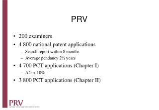
PRV(Peregrine Return Vehicle) Preliminary Design Review Benjamin Reese, Jen Getz, Jason Patterson, Greg Goldberg, Zach Hazen, David Akerman October 16, 2006
Briefing Overview • Project Objectives and Overview • Development and Assessment of System Design Alternatives • Initial Design Concepts • Aircraft Configuration • System Design to Specifications • Development and Assessment of Subsystem Design Alternatives • Project Feasibility Analysis and Risk Assessment • Project Management Plan • Questions
Project Objective Objective: To provide the Colorado Space Grant Consortium with a reusable vehicle that can return student built science payloads to a selected target.
Current Method Configuration: • Payload is tethered • Beacon sends position information • Parachute deploys after burst Issues: • Current System offers no control • Drifting occurs in ascent and descent • Launched with winds < 15 kts • Recovery a hassle • Long Hikes • Possibility of payload loss
Requirements • Vehicle and payload must not exceed 20 lbs where 10 lbs will be payload. • Vehicle structure and systems must weigh 10lbs • Vehicle must be able to carry a payload volume of 530 in3. • Vehicle size (large glider) • Vehicle must not hit the ground with a vertical velocity greater than 30 mph • Vehicle structure must be durable • Parachute required (no runway available) • Vehicle must be able to land with in a quarter mile of an intended target chosen prior to launch. • Range • Controlled descent • Account for atmospheric conditions (wind)
Mission Environment • Customer Landing site selection • Jet Stream winds with high magnitudes and varying directions • Average 92,000 ft burst altitude • Average 40 mile drift from launch site
Mission Profile • Balloon Bursts at 92,000 ft and glider is cut away. • Glider pulls out of dive and flies toward its target. • Glider adjusts dive angle to counter adverse winds • At ~1000ft above target a parachute deploys to reach required landing speed.
Glider Feasibility • L/D (5-10) provides sufficient cross-range • Wind penetration is a function of glide slope
Possible Configurations Glider Canard / Flying Wing Traditional Biplane Twin Fuselage Tandem Pros : Pros : * Potential for high * Structure Pros : L / D Pros : * Simple Airframe * Comfort with * Potential for Pros : * Structure * Potential for analysis favorable stall * More Lift per * Modular greater efficiency * Stability characteristics span * Experience * Controls * Chute Cons : deployment Cons : * Complexity Cons : Cons : * Wing * Chute * Control * Less original / Cons : Interference Deployment * Pitch Damping exciting * Design Expertise * Potential for deep stall
Design-to Specifications • Aircraft Structure Configuration • Fuselage • Must be designed to withstand up to 10 g loads in dive pullout manuver. • Must be designed to withstand parachute or brake deployment. • Must be designed to survive an impact at 10 mph with enough structural integrity to be re-used. • Wings • Must withstand 10g-loads (200 lbf) in pullout manuver.
Design-to Specifications • Aircraft Structure Configuration • Payload Bay • Payload bay must be designed to acomodate five, 105.4 in3 cubes. • Must be designed to maintain the structural integrity of the payload. • Must support a combined payload mass of 10 lb. • Must have a field of view through the fuselage for each box. • Nadir-pointing in asention phase • Zenith-pointing in glide phase • Emmpenage • Must provide control authority at low (~0-172 mph) and high (~Mach 0.9) airspeed. Note: The payload will be contained within the fuselage
Design-to Specifications • Avionics • Autopilot • Must control a 20-lb UAV at high speed (approaching Mach 0.9). • Operate at low temperatures (-70 F) and high altitude • Must withstand high G-loads (parachute deployment, high-G turns/pull-outs) • Controls/Servos • Must provide the torque necessary to apply aerodynamic forces at highairspeed (Mach 0.9)
Design-to Specifications • Avionics • Data Acquisition • Must be able to verify test flights • Video and flight data must provide proof of mission success and vehicle performance • CCD Camera w/GPS & Data Overlay • If used, Micropilot data logger on the MP2028 Autopilot will store flight data (RS-232 access) • Video Recorder • Roughly 2 GB data storage required on SD card
Design-to Specifications • Avionics • Power Supply • Must be able to provide reliable voltage and current to autopilot and servos • Must be able to provide 3 A-hrs at 8-14 VDC for avionics excluding servos • Servo battery must be able to provide 3.3 A-hrs at 4.8 VDC • Power Distribution Board • Needs to provide appropriate voltage and current to different components
Design-to Specifications • Avionics • Cable/Wiring Harness • Must be light, simple, and easy to assemble/disassemble/repair in the field • Recovery System • Must slow vehicle to safe touchdown speed (< 10 mph) during the lastphase of the descent • Must be reusable • > 90% proven reliability • Must operate independently
Subsystem Flow Diagram Auto - Pilot Communication Power System System Recovery System
Development and Assessment of Subsystem Design Alternatives • Auto-Pilot Subsystem • Micropilot MP2028g • Cost: $3300 • Excellent GUI, UAV ”setup wizard” • Onboard datalogger for flight test data • U-Nav PicoPilot-NA • Cost: $700 • Limited number of servos • Less refined integration • Untested for flights above 20,000 ft • Not recommended for aircraft over 10 lbs Subsystem Configuration Micropilot MP2028g
Development and Assessment of Subsystem Design Alternatives • Recovery System • Parachute • Ability to quickly slow glider down to acceptable landing velocity • Simple Design • Proven Technology • Deep Stall Landing • Micropilot MP2028g has flare landing capability • Auto-Pilot Failure = Recovery System Failure • Prone to collisions Subsystem Configuration Parachute with Deep Stall Maneuver
Development and Assessment of Subsystem Design Alternatives • Thermal Control Subsystem • Avionics rack temperature range -4 F<T<113 F • CCD Camera temperature T > -10 F • Heating Wire • Insulation foam • Ceramic heater • Communications Subsystem • Vehicle position tracking • Data upload possibility. • RC override possibility.
Development and Assessment of Subsystem Design Alternatives • Power Subsystem • Total flight time assumed to be 5 hours. • CCD camera, Autopilot, and GPS overlay will have fixed power consumption. • Servos will have variable power consumption based on flight conditions. • Two Batteries needed. One for servos and one for the remaining systems *ref Excel spreadsheet with average data
Sensors • 2 Pressure Sensors • To act as a failsafe in the event of GPS/autopilot failure. • Will trigger the recovery chute at an altitude of 1000 ft (±200 ft) • This corresponds to a pressure of 11 psi (±0.11 psi) • 1 External Temperature Sensor • Monitor the temperature of the external environment. • Customer request.
Project Feasibility Analysis and Risk Assessment Feasibility Break Down • The Glider Must: • Remain securely attached to balloon during ascent • Detach itself from the balloon • Gain Control after drop • Navigate to target landing area • Land Safely • Meet FAA requirements
Feasibility Breakdown • Navigate to Target Landing Area • Must cover 40 miles cross-track range against the wind • Assume no wind: is L/D feasible?
Feasibility Breakdown • Navigate to Target • Consider day where wind is strong and close to uni-directional: *Data from U Wyoming Radio Sonde
Feasibility Breakdown • Navigate to Target • Glider Airspeed
Feasibility Breakdown • Typical Simulation Result
Feasibility Breakdown • Time Integration Mission Simulation Results: • Flight Strategy is key • When to glide near L/Dmax • When to dive • Spiral maneuver may be required • Cd and wing area S values will be revisited • In strong-unidirectional wind conditions, a high drag, low L/D glider (5-10) can satisfy the range requirement with a reasonable mission strategy
Risk Analysis • Power System Failure • Auto-Pilot Failure • Parachute Failure • Unrecoverable Flight Situation • Electronics Malfunction • Loss of GPS Signal • Balloon Fails to Reach Burst Altitude
Risk Mitigation • Preliminary Experiments for CDR • Thermal model analysis • Create Auto-Pilot test bed • Prove Auto-Pilot functionality • Determine Auto-Pilot Reliability • Low Temperature • Low Battery • Create Parachute Deployment Test • Prove the parachute deployment system works • Altitude sensor controlled deployment • Shows the parachute slows 20 lbs of weight to less than 30 mph
References • Chipman, Richard R and Peter Shyprykevich. Analysis Of Wing-Body Interaction Flutter For A Preliminary space Shuttle Design. National Aeronautics and Space Administration. Washington, D.C., July 1974. • http://www.batteryspace.com/index.asp?PageAction=VIEWPROD&ProdID=2756, 2006 • Shevell, Richard S., Fundamentals of Flight. Prentice Hall, New Jersey. 1989. • Vable, Madhukar. Mechanics of Materials. 1st ed. New York: Oxford UP, Inc., 2002. • Synco, Reynders. GPSBoomerang. 12 Oct. 2006 <http://www.gpsboomerang.com/>. • Garry, Qualls. ARES. NASA. 01 Oct. 2006 <http://marsairplane.larc.nasa.gov/index.html>.
Sensor Design-to Specifications • Pressure sensor: • Sample rate: ~100Hz • 10x fmax to account for aliasing • Accuracy: <1% Full Scale • Must be able to operate at -110◦F • Temperature at 100,000 ft + FOS • Thermal Issues • A thermal analysis of the entire system is necessary. • There are several options available for controlling internal temperature. • Needs to read accurately between 0 to 100 PSI. • Analog output • Driven by group skillset.
Sensor Design-to Specifications Options: • Configurable Pressure Transducers – FP2000 Series • Small size: 3.2” x 0.5” x 1.13” • Meets pressure range requirements: 0 – 1000 PSI • Analog output: 40mV/V • Excellent accuracy: 0.1% with possible error of ±0.5% F.S. • Temperature range low value is -40 ◦F • Subminiature, Flush Diaphragm Pressure Transducers - Models G & F • Very small: 0.425” x 0.06” x 0.56” • Analog output: 2 to 5 mV/V • Excellent accuracy: 0.1% with possible error of ±0.1% F.S. • Pressure range is only 10-150 PSI • Temperature range low value is -65 ◦F
Sensor Design-to Specifications • Temperature sensor: • Sample rate: ~10Hz • 10x fmax to account for aliasing • Accuracy: <1% Full Scale • Must be able to operate at -110◦F • Temperature at 100,000 ft + FOS • Needs to read accurately between -110◦F to 80◦F • HOBO?
Sensor Design-to Specifications Options: • HOBO – Temperature Sensor • Small size: 3.2” x 0.5” x 1.13” • Meets pressure range requirements: -104◦F to 160◦F • Self contained system • Excellent accuracy: 0.1◦F with possible error of ±0.8% F.S. • Temperature range low value is -104 ◦F
Glider Scale Payload bay and aircraft to scale
Power Source Trade Study • Safety Considerations • Lithium Ion Batteries contain a lithium salt solution, which is very flammable • Lithium Polymer Batteries contain a lithium polymer, which is not flammable • Nickel Cadmium Batteries contain Cadmium, which is a heavy metal so heavy metal contamination is a possible occurrence • Nickel Metal Hydride contains a hydride absorbing alloy instead of Cadmium, which is less detrimental to the environment
Power Source Trade Study • Mass Considerations • Li-Ion Batteries have the highest energy per mass ratio of 68.03 Wh/lb. • Li-Po Batteries have the second highest energy per mass ratio of 58.96 Wh/lb. • NiCd and NiMH batteries have lowest energy per mass ratios of 13.61 and 27.21 Wh/lb, respectively.