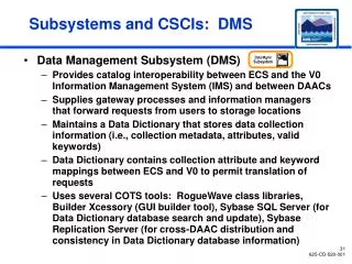
FIRST Electrical Subsystems
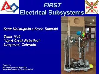
FIRST Electrical Subsystems. Scott McLaughlin & Kevin Taberski Team 1619 “Up-A-Creek Robotics” Longmont, Colorado. Thanks to Michael Dessingue (Team 250) for the beginnings of this presentation. Overview. Supplied Electronics Kit Innovation FIRST, Inc. (IFI) Hardware

FIRST Electrical Subsystems
E N D
Presentation Transcript
FIRST Electrical Subsystems Scott McLaughlin&Kevin Taberski Team 1619 “Up-A-Creek Robotics” Longmont, Colorado Thanks to Michael Dessingue (Team 250) for the beginnings of this presentation.
Overview • Supplied Electronics Kit • Innovation FIRST, Inc. (IFI) Hardware • Layout and Planning • Resistance and Ohm’s Law • Electrical Tools • Other Notes • Questions
Electronics Kit • Batteries • Charger • Wires, Cables & connectors • Cooling fans • Motors • Sensors and Camera (?) • IFI Robot Controller Items • Joystick
Battery Notes • Can work mounted on side • Should last the entire match • Mounting should be captive • If 1st year, buy one extra • Connectors will wear out, so use wire ties during a match • Use extra connectors for charger • Safety: Can deliver tremendous amounts of instantaneous current, so all connections must be protected—up to switch and circuit panel
Battery Connectors Be careful, as this previously supplied drawing is misleading. The wire does not go under the screw, it goes between the collar and the tab. You may need extra smaller heat shrink and electrical tape to make it all tight, neat and safe
IFI Hardwarehttp://www.ifirobotics.com/frc-robot-control-system-overview.shtml
Planning Your Electrical System • Plan and get electronics running early • Build test bed, and if possible make it the final-layout “bread board” so you have cabling ready for install • Can also create mechanical drawings and schematics • Think hard about the battery/cable placement… • Think about radio modem placement… • Use test bed to teach about system and test all subsystems before integrating • Communicate effectively with the mechanical sub-teams early and often about wire runs, battery, interference from moving parts, cooling, etc. • Label all wires, PWM controllers, sensors etc.
CentralizedElectronics • Pros • Easy to layout • Easy to work on • Looks neat • Easy to remove • Cons • Needs big open space on robot • Might be harder to protect electronics • Cosmetics…?
General Layout Tips • Label and/or color code everything • Secure wires (with some slack) so a hit from another robot doesn't stretch or break a wire or a connector • If in doubt, insulate • Be careful running wiring through frame so that someone doesn’t drill into it, or the insulation wears
Ohm’s Law + _ Ohm’s Law: V = I * R 12 V = I * 24 W I = 0.5 A 12 VBattery 24 W
Example FIRST Circuit 120 A Circuit Breaker Victor 884 Speed Controller + _ 40 A Circuit Breaker VoutMeasured 12 VBattery Circuit consists of 8’ of #6, 4’ of #10, and 2’ of #10. 14 Connections in the circuit
Crimp Connections • Buy a good crimper for about $20 • Home Depot, Lowes, auto parts stores, Radio Shack • Look for crimper with good handles and can used with wire gauges 10 to 24 • Consider double-action for more leverage (easier to us, but more expensive)
Wire & Crimping Notes • Use correct size wire and crimp connectors (check manual); #4 could be used for long runs but will be heavy • Auto shops have finer strand wire than say Home Deport (much easier to work with); can also get very fine strand wire, but this may only make it harder to strip • Have class on wire stripping & crimping—be prepared to use a lot of connectors and wires (but this will pay big dividends for the competition) • Can solder connections, but a good solid crimp should suffice—if you need the extra assurance go ahead and solder, but will require extra tools, classes, time and skill to do it right
Electrical Tools • Multimeter (DMM) • Voltage • Resistance • Continuity • Hand Tools • Wire Strippers • Crimpers • Side-cutters • Needle-nose • Screwdrivers • Oscilloscope • For some demonstration and testing of items such as sensors
More Battery Notes • Backup battery can discharge if RC link is established • If your battery is not lasting long, note that tank-drive and 4-wheel drive can use lots of current; also check for high loss connections • Check battery connections throughout season. A short can quickly heat up and start a fire or burn somebody. The battery voltage is not really dangerous, but the current is!!! • Don’t drop the battery!, and if the internal connections are loose, stop using the battery • Label batteries for reference
Motor Notes • Motors can get hot—but usually only during long practice sessions. Allow them to cool down if you can not put your hand on them for a few seconds. • Supplied wires on CIMs seem too small, but since they are short, is not really a problem. You will use larger gauge up to these.. • Consider using quick disconnects (spade lugs) for motor leads • Not all ‘identical’ motors are the same, and there is also directional bias—keep this in mind for autonomous modes… • Internal sparks are normal and increase as the brushes wear out
Controller Notes • Most problems are: • Low battery voltage • Poor connections • Not knowing how to setup the controller properly • Radio Frequency Interference • Understand simultaneous operation of multiple robots (i.e., Team Number Switches) • Robot-mounted radio modem should be reasonable clear of metal, wires, and ‘stuff’. • Mount robot controller for easy accessibility for serial cable and view of LEDs • Of course main breaker should have easy access
Sensor Notes • We have not used that many, yet… • Most used have been limit switches • Plan for and test early, both for electrical installation and for controller programming • Very important for autonomous mode • Harder to teach, implement and debug (be careful not to make things too complicated) • Can be mechanically tricky to mount properly
Remember • They have not given you enough time • They have given you too much to too • They have given you too much stuff • Fast, cheap, good (pick one!) • All team members are responsible for safety • Have fun, and remember it is for the kids;-) Good Luck……………………………..
Thanks Team 1619, 2006 Season