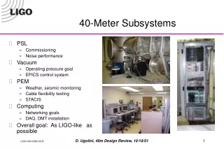
40-Meter Subsystems
40-Meter Subsystems. PSL Commissioning Noise performance Vacuum Operating pressure goal EPICS control system PEM Weather, seismic monitoring Cable flexibility testing STACIS Computing Networking goals DAQ, DMT installation Overall goal: As LIGO-like as possible. PSL Overview.

40-Meter Subsystems
E N D
Presentation Transcript
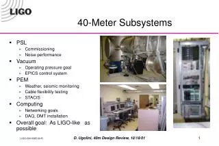
40-Meter Subsystems • PSL • Commissioning • Noise performance • Vacuum • Operating pressure goal • EPICS control system • PEM • Weather, seismic monitoring • Cable flexibility testing • STACIS • Computing • Networking goals • DAQ, DMT installation • Overall goal: As LIGO-like as possible D. Ugolini, 40m Design Review, 10/18/01
PSL Overview We use the same 10-watt Nd:YAG Lightwave 1064mm laser as the main LIGO sites, except that our master oscillator runs at 1 watt rather than 700 mW. Currently both output ports of the laser are in use, requiring two sets of cylindrical lenses to correct its astigmatism. We need to pickoff the low-power beam after the periscope, and rethink the circularity and mode-matching. D. Ugolini, 40m Design Review, 10/18/01
PSL Design Requirements • Transmission: ~8 W through PMC, ~6 W to IFO • FSS servo requirements • Unity gain frequency = 500-800 kHz • Frequency noise limits • 0.1 Hz/Hz at 100 Hz • 0.01 Hz/Hz at 1kHz to 10kHz • PMC servo requirements • Unity gain frequency = 600 Hz • Frequency noise limits • 4100 Hz/Hz at 40 Hz • 165 Hz/Hz at 100 Hz • 16.5 Hz/Hz at 1kHz • 1.65 Hz/Hz at 10 kHz From the PSL Final Design Report, LIGO-T990025-00-D D. Ugolini, 40m Design Review, 10/18/01
Mode Matching in FSS Path Reference cavity visibility = 93% Transmitted power = 5 mW D. Ugolini, 40m Design Review, 10/18/01
Mode Matching in PMC Path PMC cavity visibility = 64% Transmitted power = 5.2 W D. Ugolini, 40m Design Review, 10/18/01
Positional/Angular Stability QPD measurements taken over 72 hours, 8/17/01-8/20/01 D. Ugolini, 40m Design Review, 10/18/01
PMC Servo Noise Performance PZT resonance Notch filter D. Ugolini, 40m Design Review, 10/18/01
FSS Servo Noise Performance D. Ugolini, 40m Design Review, 10/18/01
What’s Wrong With the FSS? • Photo at right shows the FSS error signal. • 7 MHz oscillation in tail • “Zigzag” at zero crossing • What’s causing this? • Bad servo/mixer? Swapped out with no change • LO signal too small? 5 Vpp from FSS reference card • RFPD signal too small? 2 mW of light at resonance D. Ugolini, 40m Design Review, 10/18/01
Future PSL Work • Review optical layout • Pick off low-power beam after periscope • Select new cylindrical lenses for better circularity • New mode-matching scheme in both paths by M. Smith • More dramatic change in layout (fewer turns)? • Diagnose excess FSS noise • Install EOMs, relocate QPDs to final position • Final refinements • Anodized beam tubes in both paths • Heating jacket for reference cavity • Higher reflectivity curved mirror for PMC • PSL ready for arrival of MC optics in January D. Ugolini, 40m Design Review, 10/18/01
Vacuum System Overview • Expanded envelope -- MC, OOC chambers added • Regenerated, reinstalled ion pumps • Contaminant level unchanged; opted for no bake-out H2O N2 O2 H2 Ar CO2 D. Ugolini, 40m Design Review, 10/18/01
EPICS-based Control System D. Ugolini, 40m Design Review, 10/18/01
Residual Gas Noise Requirement The plot at left includes the residual gas noise for a vacuum of 10-6 torr, dominated by water and nitrogen. At higher pressures the noise becomes significant at the tuned frequency. The 40m vacuum system can run as low as 3*10-7 torr, and has a pressure of 1.3*10-6 torr in low-vibration mode (ion pumps only). D. Ugolini, 40m Design Review, 10/18/01
Future Vacuum System Work • Hardware installation nearly complete • Still need to install new filter at vent valve • Single O-ring at OOC; permeation only significant at 10-8 torr • Turbopumps obsolete by next year; should they be replaced? • Improvements to EPICS control system • Ion pump voltage, current, status readout (crash problem) • Turbopump status, rotation speed readout (no response) • Read out RGA alarm status • Recognition of system state • Automated state changes • Begin logging RGA scans, system status D. Ugolini, 40m Design Review, 10/18/01
PEM: Weather Station D. Ugolini, 40m Design Review, 10/18/01
PEM: Particle Counter D. Ugolini, 40m Design Review, 10/18/01
PEM: Seismic Monitoring 4.2 earthquake in Westwood, CA (roughly 20 miles SW of Caltech) at 5pm on September 9th, 2001 D. Ugolini, 40m Design Review, 10/18/01
Cable Flexibility Testing There has been concern that the in-vacuum cables used at the sites are too stiff, and would short out the 40m seismic stacks. Larry Jones has been acquiring cable prototypes, which are tested with the apparatus shown here. The cables are clamped to the MC end chamber seismic stack, which is then vertically shaken. Wilcoxon accelerometers are used to measure the transfer function. D. Ugolini, 40m Design Review, 10/18/01
Flexibility Testing Results mechanical short D. Ugolini, 40m Design Review, 10/18/01
STACIS Active Seismic Isolation • One set of 3 for each of 4 test chambers • 6-dof stiff PZT stack • Active bandwidth of 0.3-100 Hz, • 20-30dB of isolation • passive isolation above 15 Hz. D. Ugolini, 40m Design Review, 10/18/01
Future PEM Work • Fix, understand current devices • Outside humidity stuck at 128% • Weather station, particle counter do not agree • Add more sensors (microphone, line monitor, etc.) • Read STACIS information into EPICS, DAQ • “Black box” software, must reverse-engineer • Start looking for correlations with IFO performance D. Ugolini, 40m Design Review, 10/18/01
40m Network Diagram General Computing rana (gateway) General usage PCs, Suns, printers Martian network DAQ scipes Fast Ethernet Fiber network system dmt40m br40m fb40m RAID cdssol6 op240m scipes Frame Broadcaster Frame Builder Vacuum Control Room CACR(?) op140m Automounts Automounts Shared Disk D. Ugolini, 40m Design Review, 10/18/01
Data Acquisition System • The 40m DAQ is a mini-version of DAQ at the sites: • ADCU with two ICS-110B modules (64 fast channels) • EDCU for reading values from EPICS (currently 79 slow channels) • RAID array with hundreds of GB of frame storage space: • Full data for 48 hours • Second trend frames for one month • Longer trend frames “forever” • Frame broadcaster for use with DMT (still being installed) • Connection to CACR for permanent data storage? D. Ugolini, 40m Design Review, 10/18/01
Future Computing Work • Populate op140m shared disk • Move state code, medm screens, DAQ code, etc. • Point all VME crates to boot from op140m • Finish DMT installation • J. Zweizig has just installed software on dmt40m; we’re still learning how it all works • R. Bork, A. Ivanov are preparing br40m • Send EPICS screens, values to web server D. Ugolini, 40m Design Review, 10/18/01
Summary • The 40m PSL is up and running, but needs further commissioning work to increase its power output and reduce the frequency noise in the FSS • The vacuum system meets the goal of operating vibration-free at ~10-6 torr • Several PEM components are in place (weather & seismic monitoring) and more are being added • The DAQ is functioning, and DMT is being installed • These systems should be ready for the arrival of MC optics in January! D. Ugolini, 40m Design Review, 10/18/01