Download
1 / 51
590 likes | 976 Vues
Chapter 12 Expendable-Mold Casting Processes (II) EIN 3390 Manufacturing Processes Spring, 2012 . Molds and cores can receive strength from the addition of 3-6% sodium silicate (Water Glass) Remains soft and moldable until it is exposed to CO 2

E N D
Chapter 12Expendable-Mold Casting Processes(II)EIN 3390 Manufacturing ProcessesSpring, 2012
Molds and cores can receive strength from the addition of 3-6% sodium silicate (Water Glass) • Remains soft and moldable until it is exposed to CO2 • Na2SiO3+CO2 ->Na2CO3+SiO2 (Colloidal) • Hardened sands have poor collapsibility • Difficult for shakeout and core removal • Heating from pour makes the mold stronger Sodium Silicate-CO2 Molding
Involves room-temperature chemical reactions • Organic and inorganic resin binders can be mixed with the sand before the molding operation • Curing reactions begin immediately • No-bake sand can be compacted by light vibrations • Wood, plastic, fiberglass, or Styrofoam can be used as patterns • System selections are based on the metal being poured, cure time desired, complexityand thickness of the casting, and the possibility of sand reclamation No-Bake, Air-Set, or Chemically Bonded Sands
High dimensional precision and good surface finish • For almost all engineering metals • Good hot strength • High resistance to mold-related casting defects • Molds decompose readily after the metal has been poured, providing good shakeout • Cost of no-bake molding is about 20-30%more than green-sand molding • Limited to low-medium production quantities No-Bake Sands Air-Set, or Chemically Bonded Sands
Basic steps • Individual grains of fine silica sand are precoated with a thin layer of thermosetting resin and heat-sensitive liquid catalyst. • A metal pattern (usually some form of cast iron) is preheated to 230 – 3150c • Heat from the pattern partially cures a layer of material • A strong, solid-bonded region adjacent to the pattern is formed in 10-20 mm in thickness. 2) Pattern and sand mixture are inverted and only the layer of partially cured material remains 3) The pattern with the shell is placed in an oven and the curing process is completed Shell Molding
Basic steps (- continue) 4) Hardened shell is stripped from the pattern 5) Shells are clamped or glued together with a thermoset adhesive 6) Shell molds are placed in a pouring jacket and surrounded with sand, gravel, etc. for extra support Casting Materials: Casting irons, alloys of aluminum, and copper Shell Molding
Advantages: • Excellent dimensional accuracy with tolerance of 0.08 – 0.13 mm • Very smooth surfaces • Excellent Collapsibility and permeability • Less cost of cleaning, and machining • Less amount of required mold material • High productivity, low labor costs. Shell Molding
Disadvantages: • Cost of a metal pattern is often high • Design must include the gate and the runner • Expensive binder • Limited Part size Shell Molding
Figure 12-18 Schematic of the dump-box version of shell molding. a) A heated pattern is placed over a dump box containing granules of resin-coated sand. b) The box is inverted, and the heat forms a partially cured shell around the pattern. c) The box is righted, the top is removed, and the pattern and partially cured sand is placed in an oven to further cure the shell. d) The shell is stripped from the pattern. e) Matched shells are then joined and supported in a flask ready for pouring. Dump-Box Shell Molding
Figure 12-19 (Top) Two halves of a shell-mold pattern. (Bottom) The two shells before clamping, and the final shell-mold casting with attached pouring basin, runner, and riser. (Courtesy of Shalco Systems, Lansing, MI.) Shell-Mold Pattern
V-process or vacuum molding • Vacuum serves as the sand binder • Applied within a specific vented pattern, drawing the sheet tight to its surface • Flask is filled with vibrated dry, unbonded sand • Compacts the sand and gives the sand its necessary strength and hardness • When the vacuum is released, the pattern is withdrawn Other Sand-Based Molding Methods
Figure 12-20 Schematic of the V-process or vacuum molding. A) A vacuum is pulled on a pattern, drawing a heated shrink-wrap plastic sheet tightly against it. b) A vacuum flask is placed over the pattern and filled with dry unbonded sand, a pouring basin and sprue are formed; the remaining sand is leveled; a second heated plastic sheet is placed on top; and a mold vacuum is drawn to compact the sand and hold the shape. c) With the mold vacuum being maintained, the pattern vacuum is then broken and the pattern is withdrawn. The cope and drag segments are assembled, and the molten metal is poured. V-Process
Advantages • Absence of moisture-related defects • Binder cost is eliminated • Sand is completely reusable • Finer sands can be used • Better surface finish • No fumes generated during the pouring operation • Exceptional shakeout characteristics Advantages and Disadvantages of the V-Process
Disadvantages • Relatively slow process • Used primarily for production of prototypes • Low to medium volume parts • More than 10 but less than 50,000 Advantages and Disadvantages of the V-Process
Complex internal cavities can be produced with cores • Cores can be used to improve casting design • Cores may have relatively low strength • If long cores are used, machining may need to be done afterwards • Green sand cores are not an option for more complex shapes 12.3 Cores and Core Making
Produced separate from the remainder of the mold • Inserted into core prints that hold the cores in position • Dump-core box • Sand is packed into the mold cavity • Scrap level with top surface (like paring line) • Invert box and leave molded sand on a plate • Sand is baked or hardened • Single-piece cores in a split-core box • Two-halves of a core box are clamped together Dry-Sand Cores
Figure 12-21 V-8 engine block (bottom center) and the five dry-sand cores that are used in the construction of its mold. (Courtesy of General Motors Corporation, Detroit, MI.) Dry-Sand Cores
Core-oil process (1% vegetable oil) • Sand is blended with oil to develop strength • Wet sand is blown or rammed into a simple core box • In convection ovens at 200 – 2600c for curing • Hot-box method • Sand is blended with a thermosetting binder • Heat to 230 0c for curing • Cold-box process • Binder coated sand is packed and then sealed • Gas or vaporized catalyst polymerizes the resin Additional Core Methods
Figure 12-22 (Left) Four methods of making a hole in a cast pulley. Three involve the use of a core. Figure 12-23 (Right) Upper Right; A dump-type core box; (bottom) core halves for baking; and (upper left) a completed core made by gluing two opposing halves together. Additional Core Methods
Air-set or no-bake sands may be used • Eliminate gassing operations • Reactive organic resin and a curing catalyst • Shell-molding • Core making alternative • Produces hollow cores with excellent strength • Selecting the proper core method is based on the following considerations • Production quantity, production rate, required precision, required surface finish, metal being poured Additional Core Considerations
Sufficient strength before hardening • Sufficient hardness and strength after hardening • Smooth surface • Minimum generation of gases • Adequate permeability • Adequate refractoriness • Good collapsibility Casting Core Characteristics
Addition of internal wires or rods • Vent holes formed by small wire into core • Cores can be connected to the outer surfaces of the mold cavity • Core prints • Chaplets- small metal supports that are placed between the cores and the mold cavity surfaces and become integral to the final casting Techniques to Enhance Core Properties
Figure 12-24 (Left) Typical chaplets. (Right) Method of supporting a core by use of chaplets (relative size of the chaplets is exaggerated). Chaplets
Mold Modifications • Cheeks are second parting lines that allow parts to be cast in a mold with withdrawable patterns • Inset cores can be used to improve productivity Figure 12-26 (Right) Molding an inset section using a dry-sand core. Figure 12-25 (Left) Method of making a reentrant angle or inset section by using a three-piece flask.
Plaster mold casting • Mold material is made out of plaster with additives to improve green strength, dry strength, permeability, and castability • Slurry is poured over a metal pattern • Hydration of plaster produces a hard mold • Bake plaster mold to remove excess water • Improved surface finish and dimensional accuracy • Limited to the lower-melting-temperature nonferrous alloys 12.4 Other Expendable-Mold Processes with Multiple-Use Patterns
Antioch process • Variation of plaster mold casting • 50% plaster, 50% sand mixed with water • Improvement of permeability and reduce solidification time 12.4 Other Expendable-Mold Processes with Multiple-Use Patterns
Mold is made from ceramic material • Ceramics can withstand higher temperatures • Greater cost and not reusable for mold • Shaw process • Reusable pattern inside a slightly tapered flask • Mixture sets to a rubbery state that allows the part and flask to be removed • Mold surface is then ignited with a torch Ceramic Mold Casting
Figure 12-27 Group of intricate cutters produced by ceramic mold casting. (Courtesy of Avnet Shaw Division of Avnet, Inc., Phoenix, AZ) Ceramic Mold Casting
Expendable graphite molds • Some metals are difficult to cast • Titanium • Reacts with many common mold materials • Powdered graphite can be combined with additives and compacted around a pattern • Mold is broken to remove the product • Rubber-mold casting • Artificial elastomers can be compounded in liquid form and poured over the pattern to produce a semirigid mold • Limited to small castings and low-melting-point materials Other Casting Methods
12.5 Expendable-Mold Processes Using Single-Use Patterns • Investment casting • One of the oldest casting methods • Products such as rocket components, and jet engine turbine blades • Complex shapes • Most materials can be casted Figure 12-30 Typical parts produced by investment casting. (Courtesy of Haynes International, Kokomo, IN.)
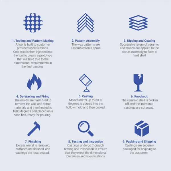
Sequential steps for investment casting 1) Produce a master pattern 2) Produce a master die 3) Produce wax patterns 4) Assemble the wax patterns onto a common wax sprue 5) Coat the tree with a thin layer of investment material 6) Form additional investment around the coated cluster Investment Casting
Sequential steps for investment casting (- continue) 7) Allow the investment to harden 8) Remove the wax pattern from the mold by melting or dissolving 9) Heat the mold 10) Pour the molten metal 11)Remove the solidified casting from the mold Investment Casting
Advantage • Complex shapes can be cast • Thin sections, down to 0.4 mm can be made • Excellent dimensional precision • Very smooth surface • Machining can be eliminated or reduced • Easy for process steps automation • Disadvantage • Complex process • Costly for die Quantity of investment casting 100 – 10,000/year Advantages and Disadvantages of Investment Casting
Investment Casting Figure 12-28 Investment-casting steps for the flask-cast method. (Courtesy of Investment Casting Institute, Dallas, TX.)
Investment Casting Figure 12-28 Investment-casting steps for the flask-cast method. (Courtesy of Investment Casting Institute, Dallas, TX.)
Investment Casting Figure 12-29 Investment-casting steps for the shell-casting procedure. (Courtesy of Investment Casting Institute, Dallas, TX.)
Investment Casting Figure 12-29 Investment-casting steps for the shell-casting procedure. (Courtesy of Investment Casting Institute, Dallas, TX.)
Pouring process is upside down • Vacuum is used within the chamber • Draws metal up through the central sprue and into the mold • Free of slag and dross • Low level of inclusions • Little turbulence • Improved machinability • Mechanical properties approach those of wrought material • Simpler gating systems • Lower pouring temperatures • Improved grain structure and better surface finish Counter-Gravity Investment Casting
Reusable patterns can complicate withdrawal • May mandate design modifications • Evaporative pattern processes • Pattern is made of expanded polystyrene (EPS)or polymethylmethacrylate (EPMMA) • Pattern remains in the mold until the molten metal melts away the pattern • If small quantities are required, patterns may be cut by hand • Material is lightweight Evaporative Pattern (Full-Mold and Lost-Foam) Casting
Metal mold or die is used to mass-produce the evaporative patterns • Pattern: 2.5% polymer, 97.5% air • For multiple and complex shapes, patterns can be divided into segments or slices • Assembled by hot-melt gluing • Full-mold process • Green sand is compacted around the pattern and gating system Evaporative Patterns
Lost-foam: (see Figure 12-32) • Make polystyrene pattern assembly • Make a thin refractory coating for Polystyrene pattern • Place dried pattern into a flask surrounded by fine unbounded sand • Compact sand by vibration • Pour molten metal onto pattern • Dump sand and remove casting from flask • Backup sand can be reused Evaporative Patterns
Lost Foam Process Figure 12-32 Schematic of the lost-foam casting process. In this process, the polystyrene pattern is dipped in a ceramic slurry, and the coated pattern is then surrounded with loose, unbonded sand.
Sand can be reused • Castings of almost any size • Both ferrous and nonferrous metals • No draft is required • Complex patterns • Smooth surface finish • Cores are not required • Absence of parting lines • Higher metal yield Advantages of the Full-Mold and Lost-Foam Process
Figure 12-33 The stages of lost-foam casting, proceeding counterclockwise from the lower left: polystyrene beads→ expanded polystyrene pellets → three foam pattern segments → an assembled and dipped polystyrene pattern → a finished metal casting that is a metal duplicate of the polystyrene pattern. (Courtesy of Saturn Corporation, Spring Hill, TN.) Lost-Foam Casting
Final step of casting involves separating the molds and mold material • Shakeout operations • Separate the molds and sand from the flasks • Punchout machines • Force entire contents of a flask from a contaner • Vibratory machines • Rotary separators • Remove sand from casting (iron, steel, brass) • Blast cleaning • Remove sand, oxide scale, parting line burrs. 12.6 Shakeout, Cleaning, and Finishing
Different expendable-mold casting processes are developed to create shaped containers, and then utilize liquid fluidity and subsequent solidification to produce desired shapes of casting products. • Each process has unique advantages and disadvantages • Best method is chosen based on the product shape, material and desired properties 12.7 Summary