Download
1 / 12
120 likes | 144 Vues
Learn about depositing copper onto silicon wafers using electrochemical deposition, replacing silver with copper for higher conductivity and less resistivity. Explore the process of photolithography, calculating amps needed, and more.

E N D
Microscale Device Fabrication:Electrochemical Deposition (EMD) of Metals By Mahmoud Hayat and Cerise McLaren
The Project The goal of the project is to deposit copper onto a pattern that is put on a silicon wafer. The copper deposit on the pattern creates a circuit on the silicon wafer. Copper is being used instead of a previously more commonly used silver because it has a greater conductivity and less resistivity than silver. The silicon wafer will be used as a printed circuit board (PCB) that are found in a variety of different mechanical equipment, such as computers and cell phones.
Day One: In the Lab This is a photograph of our work station. This is a setup of the electrochemical deposition of copper wires. In this experiment copper is transferred from a positively charged wire to a negatively charged wire in a solution made of H2SO4, HCL, CuSO4 and H2O. The negatively charged wire becomes thicker with copper and the positively charged wire becomes thinner.
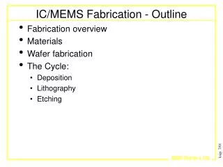
Day Two:IME Manufacturing LabPhotolithography The Process: • Clean silicon wafer with acetone, methanol and DI water. Blow dry with nitrogen gas. • Soft bake wafer at 90o C for two minutes. • Place wafer on spinner; turn on vacuum to prevent wafer from moving. Add 24 drops photo resist in center of wafer and start the spinner. • Hard bake wafer at 120o C for ten minutes.
Place wafer under a mask that has a pattern where copper will be deposited onto the aluminum plated silicon wafer. Expose wafer to ultraviolet light for 30 seconds. Immerse wafer in developing solution for three to four minutes. Clean wafer with DI water and blow dry with nitrogen gas. • Soft bake wafer for two minutes and check the pattern on the wafer under a microscope. • The wafer is now ready for electrochemical deposition. The wafers after the photolithography process.
Equipment in the IME Manufacturing Lab Acetone, methanol and DI water used to clean the wafers The lab equipment Ovens and masking machine Spin coater
Day Three: Deposition of Copper alligator clips solution power source mixer After creating an image on the silicon wafer the electrochemical deposition of copper can begin. The first step is to make the solution. After mixing the solution the beaker is to be placed on the mixer that uses a magnet stir bar to stir liquids. The surface area of the exposed spots on the silicon wafer are measured and put into an equation to calculate the amps needed to deposit copper onto the wafer. A piece of copper wire or sheet of copper is placed in the beaker with the positive alligator clip, held in place and allowed to sit in the solution. The silicon wafer is placed in the beaker with the negative alligator clip, held in place with the image side facing the piece of copper and allowed to sit in the solution about two or three centimeters from the piece of copper. The mixer is turned on at a medium speed and the power source is turned on to the amps that were calculated from the surface area. The process usually takes about twenty five minutes.
Day Three: Results and Conclusions Results The expected result of the electrochemical deposition experiment was that copper would be deposited on the exposed pattern on the silicon wafer. The two wafers that were used in the experiments were not deposited with copper or had very small trace amounts of copper. Conclusion The possible reasons that the exposed areas on the wafer did not become deposited with copper are the following: 1) The aluminum plating on the silicon wafer was very thin. Because of this, the current travelling form the power source was not strong enough because the thin aluminum was not thick enough to allow a strong current. 2) The silicon wafers may have been defected in the process of photolithography, such as being scratched or touched with invasive chemicals.
The Grand Conclusion What we learned and what we could have done better • This project taught us… • how to mix chemicals properly and safely • how to deposit copper onto other metals • the process of photolithography • how silicon wafers are made and what they are used for • how to calculate amps needed for a specific surface area • how to work as a team
Electromechanical Deposition of Copper: The Fun Stuff These are pieces of aluminum and brass that were deposited with copper
Acknowledgements Partial support for this work was provided by the Intel Faculty Fellowship and the National Science Foundation’s Course, Curriculum and Laboratory Improvement Program under grant DUE-0127175