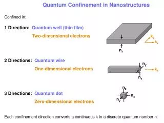
2D Nanostructures
2D Nanostructures. Thin Films. Film growth methods Vapour-phase deposition Evaporation Molecular beam epitaxy (MBE) Sputtering Chemical vapour deposition (CVD) Atomic Layer deposition (ALD) Liquid-based growth Electrochemical deposition Chemical Bath deposition (CBD or CSD )

2D Nanostructures
E N D
Presentation Transcript
2D Nanostructures Thin Films
Film growth methods • Vapour-phase deposition • Evaporation • Molecular beam epitaxy (MBE) • Sputtering • Chemical vapour deposition (CVD) • Atomic Layer deposition (ALD) • Liquid-based growth • Electrochemical deposition • Chemical Bath deposition (CBD or CSD) • Langmuir-Blodgett films • Self-assembled monolayers (SAMs)
Film deposition • Involves predominantly heterogeneous processes • Heterogeneous chemical reactions • Evaporation • Adsorption & desorption on growth surfaces • Heterogeneous nucleation & surface desorption on growth surfaces • Most film deposition & characterization processes are conducted under vacuum
Fundamentals of film growth • Thin film growth involves nucleation and growth on the substrate or growth surface • Crystallinity & microstructure of film is determined by nucleation process • 3 Basic nucleation modes • Island growth • Growth species are more strongly bonded to each other than to the substrate • Islands coalesce to form a continuous film • E.g. metals on insulator substrates, alkali halides, graphite and mica substrates • Layer growth • Growth species are bound more strongly to the substrate than to each other • 1st complete monolayer is formed before the deposition of 2nd layer occurs • Involves in situ developed stress due to lattice mismatch between the deposit and the substrate • e.g. epitaxial growth of single crystal films • Island-layer growth • combination of layer growth and island growth
Effect of growth conditions • Nucleation models and mechanisms are applicable to the formation of single crystal, polycrystalline and amorphous deposit, and of inorganic, organic and hybrid deposit • Whether the deposit is single crystalline, polycrystalline or amorphous depends on the growth conditions and the substrate
Growth of single crystal films is most difficult and requires: • Growth of single crystal films is most difficult and requires: • (i) a single crystal substrate with a close lattice match • (ii) a clean surface so as to avoid possible 2o nucleation • (iii) a high growth temperature so as to ensure sufficient mobility of the growth species • (iv) low impinging rate of growth species so as to ensure sufficient time for surface diffusion and incorporation of growth species into the crystal structure and for structural relaxation before the arrival of next growth species
Deposition of amorphous films • Deposition of amorphous films typically occurs • (i) when a low growth temperature is applied, there is a insufficient surface mobility of growth species, and/or • (ii) When the influx of growth species onto the growth surface is very high, growth species does not have enough time to find the growth sites with the lowest energy.
Growth of polycrystalline crystalline films • Conditions for the growth of polycrystalline films • Intermediate between conditions of single crystal growth and amorphous film deposition • moderate temperature to ensure a reasonable surface mobility of growth species • High impinging flux of growth species
Epitaxy • The growth or formation of single crystal on top of a single crystal substrate • Homoepitaxy • is to grow film on the substrate, in which both are the same material • No lattice mismatch between films and substrates • Uses • to grow better quality film • to introduce dopants into the grown film • Heteroepitaxy • Films & substrates are different materials • Lattice mismatch between films and substrates • Application of epitaxy: electronic industry
Physical vapour deposition (PVD) • PVD is a process of transferring growth species from a source or target and deposit them on a substrate to form a film. • The process proceeds atomically and mostly involves no chemical reactions. • Methods for the removal of growth species • Evaporation • The growth species are removed from the source by thermal means • Sputtering • Atoms or molecules are dislodged from solid target through impact of gaseous ions (plasma)
humidifier Aerosol-assisted chemical vapor deposition (AACVD)
Low pressure metal-organic chemical vapor deposition (LP-MOCVD)
Evaporation • The desired vapour pressure of source material can be generated by simply heating the source to elevated temperatures • The concentration of the growth species in the gas phase can be easily controlled by varying the source temperature and the flux of the carrier gas • The resulting vapour composition often differs from the source composition due to pyrolysis, decomposition and dissociation • It is difficult to deposit complex films. When a mixture of elements or compounds is used as a source for the growth of a complex film • One element may evaporate faster than the another resulting in the depletion of the first element • Deposition of thin films by evaporation is carried out in a low pressure (10-3 ~10-10 torr). It is difficult to obtain a uniform thin film over a large area. • To overcome this shortfall • Multiple sources are used instead of single point source • The substrate is rotated • Both source and substrate are loaded on the surface of a sphere
Sputtering • Sputtering is to use energetic ions to knock atoms or molecules out from a target that acts as one electrode and subsequently deposit them on a substrate acting as another electrode
Sputtering…dc discharge system • Ionization of inert gas e.g. Ar (by electric field or dc voltage) • when inert gas ions strike the cathode (source target), neutral target atoms are ejected • These atoms pass through the discharge and deposit on the opposite electrode (the substrate with growing film • Other negatively charged species also bombard and interact with the surface of the substrate or grown film
Deposition of insulating film • Apply an alternate electric field to generate plasma between two electrodes • Typical RF frequencies: 5 – 30 MHz • 13.56 MHz reserved for plasma processing by the Federal Communications Commission • The target self-biases to a negative potential and behaves like a dc target • Electrons are more mobile than ions and have little difficulty in following the periodic change in the electric field • To prevent simultaneous sputtering on the grown film or substrate, the sputter target must be an insulator and be capacitatively coupled to the RF generator • Sputtering a mixture of elements/compounds will not result in a change of composition in the target and thus the composition of the vapour phase will be the same as that of the target and remain the same during the deposition.
Laser ablation • Uses laser beams to evaporate the material • Absorption characteristics of the material to be evaporated determine the laser wavelength to be used • Pulsed laser beams are generally used in order to obtain high power density. • Laser ablation is an effective technique for the deposition of complex metal oxides such as high Tc superconductor films. • Advantage of Laser ablation • The composition of the vapour phase can be controlled as that in the source • Disadvantage of Laser ablation • Complex system design • Not always possible to find desired laser wavelength for evaporation • Low energy conversion efficiency
Electron beam evaporation • Limited to electrically conductive source • Advantages • Wide range of controlled evaporation rate due to a high power density • Low contamination
Arc evaporation • Used for evaporation of electrically conductive source.
Molecular beam epitaxy (MBE) • A special case of evaporation for single crystal film growth, with highly controlled evaporation of a variety of sources in ultrahigh-vacuum of typically ~10-10 torr. • Consists of realtime structural and chemical characterization capability • (high energy electron diffraction (RHEED) • X-ray photoelectric spectroscopy (XPS) • Auger electron spectroscopy (AES) • Can also be attached to other analytical instruments
MBE • In MBE the evaporated atoms or molecules from one or more sources do not interact with each other in the vapour phase under such low pressure • Most molecular beams are generated by heating solid materials placed in source cells (aka effusion cells or Knudssen cells) • The atoms or molecules striking on the single crystal substrate results in the formation of the desired epitaxial film. • The extremely clean environment, the slow growth rate, and independent control of the evaporation of individual sources enable the precise fabrication of nanostructures and nanomaterials at a single atomic layer • Highly pure film can be obtained • UH vacuum environment ensures absence impurity or contamination • Minimal formation of crystal defects • Slow growth rate ensures sufficient surface diffusion and relaxation • Precise control of chemical composition of the deposit possible • Evaporation of sources controlled individually
Main attributes of MBE • A low growth temperature that limits diffusion and hyper abrupt interfaces • A slow growth rate that ensures a well controlled 2D growth at a rate of 1 μm/h. A very smooth surface and interface is achievable through controlling the growth at the monoatomic layer level. • A simple growth mechanism compared to other film growth techniques ensures better understanding due to the ability of individually controlled evaporation of sources • A variety of in situ analysis capabilities provide invaluable information for the understanding and refining of the process
Atomic Layer Deposition (ALD) • ALD is aka - atomic layer epitaxy (ALE) - atomic layer growth (ALG) - atomic layer CVD (ALCVD) - molecular layer epitaxy (MLE) • differs significantly from other thin film deposition methods. • The most distinctive feature of ALD is self-limiting growth nature, each time only one atomic or molecular layer can grow. • Therefore, ALD offers the best possibility of controlling the film thickness and surface smoothness in truly nanometer or sub-nanometer range. • ALD can be considered as a special modification of the chemical vapor deposition, or a combination of vapor-phase self-assembly and surface reaction. • Typical ALD process • Surface is first activated by chemical reaction. • When precursor molecules are introduced into the deposition chamber, they react with the active surface species and form chemical bonds with the substrate. • Since the precursor molecules do not react with each other, no more than one molecular layer could be deposited at this stage. • Next, the monolayer of precursor molecules that chemically bonded to the substrate is activated again through surface reaction. • Either the same or different precursor molecules are subsequently introduced to the deposition chamber and react with the activated monolayer previously deposited. • As the steps repeat, more molecular or atomic layers are deposited in the way one layer at a time.
The process of titania film growth by ALD. • Substrate Hydroxylation • Introduction of titanium precursor (titanium tetrachloride). • Precursor will react with the surface hydroxyl groups through a surface condensation reaction • Cl3Ti-O-Me + H2O → (HO)3Ti-O-Me + HCl • Neighboring hydrolyzed Ti precursors subsequently condensate to form Ti-O-Ti linkage: • (HO)3Ti-O-Me + (HO)3Ti-O-Me →Me-O-Ti(OH)2-O-Ti (HO)2-O-Me + H2O • By-product HCl and excess H2O removed from the reaction chamber.
ZnS film growth • Precursors: ZnCl2 and H2S • Chemisorb ZnCl2 on substrate • Introduce H2S to react with ZnCl2 to deposit a monolayer of ZnS on substrate • HCl is released as a by-product.
Advantages of ALD (compared to other vapor phase deposition methods) • (1) precise control of film thickness • due to the nature of self-limiting process, and the thickness of a film can be set digitally by counting the number of reaction cycles. • (2) conformal coverage. • due to the fact that the film deposition is immune to variations caused by nonuniform distribution of vapor or temperature in the reaction zone.
Applications and limitations of ALD • ALD is an established technique for the production of large area electroluminescent displays, and is a likely future method for the production of very thin films needed in microelectronics. • Limitations • Many other potential applications of ALD are discouraged by its low deposition rate, typically <0.2 nm (less than half a monolayer) per cycle.
Self Assembly • Self-assembly • is a process in which a set of components or constituents spontaneously forms an ordered aggregate through their global energy minimization. • is a process that ordered arrangement of molecules and small components such as small particles occur spontaneously under the influence of certain forces such as chemical reactions, electrostatic attraction, and capillary forces. • Macromolecules (e.g. proteins, nucleic acid sequences, micelles, liposomes, and colloids)in nature adapt their final folding and conformation by self-assembly processes. • Self-assembled monolayers or multiple layers of molecules • In general, chemical bonds are formed between the assembled molecules and the substrate surface, as well as between molecules in the adjacent layers. • The major driving force here is the reduction of overall chemical potential. • A SAM is defined as a 2-D film with the thickness of one molecule that is attached to a solid surface through a covalent bond.
Self-assembled monolayers (SAMs) • SAMs are molecular assemblies that are formed spontaneously by the immersion of an appropriate substrate into a solution of an active surfactant in an organic solvent.
SAMs…3 Parts of a self-assembling surfactant molecule : • The head group that chemisorbs on the substrate surface. • very strong molecular-substrate interactions (e.g. covalent Si-O and S-Au bonds, ionic –CO2--Ag+ bond. • The alkyl chain. • The third molecular part is the terminal functionality • surface functional groups in SAMs are thermally disordered at room temperature. .
SAMs • The driving force for the self-assembly includes • electrostatic force • hydrophobicity and hydrophilicity • capillary force • chemisorption. • Types of self-assembly methods for the organic monolayers include • (1) organosilicon on hydroxylated surfaces, such as SiO2 on Si, Al2O3 on Al, glass, • (2) alkanethiols on gold, silver, and copper, • (3) dialkyl sulfides on gold, • (4) dialkyl disulfides on gold, • (5) alcohols and amines on platinum, and • (6) carboxylic acids on aluminum oxide and silver. • Self-assembly methods grouped based on the types of chemical bonds formed between the head groups and substrates. • (1) covalent Si-O bond between organosilicon on hydroxylated substrates that include metals and oxides, • (2) polar covalent S-Me bond between alkanethiols, sulfides and noble metals such as gold, silver, platinum, and copper, and • (3) ionic bond between carboxylic acids, amines, alcohols on metal or ionic compound substrates. • Application of self-assembly: • the introduction of various desired functionalities and surface chemistry to the inorganic materials.
Monolayers of Organosilicon or Alkylsilane Derivatives • Alkylsilanes: RSiX3, R2SiX2, or R3SiX, where X = chloride or alkoxy and R = a carbon chain that can bear different functionalities, such as amine or pyridinyl. • The formation of monolayers is simply by reacting alkylsilane derivatives with hydroxylated surfaces such as SiO2, TiO2.
Monolayers of Organosilicon or Alkylsilane Derivatives • Introduction of a hydroxylated surface into a solution of alkyltrichlorosilane in an organic solvent • After immersion, the substrate is rinsed with methanol, DI water and then dried. • Organic solvent is in general required for the self-assembly for the alkylsilane derivatives, since silane groups undergo hydrolysis and condensation reaction when in contact with water, resulting in aggregation. • For alkylsilanes with more than one chloride or alkoxy groups, surface polymerization is commonly invoked deliberately by the addition of moisture, so as to form silicon-oxygen-silicon bonds between adjacent molecules.
Multilayers of Organosilicon or Alkylsilane Derivatives • The construction of an SA multilayer requires that the monolayer surface be modified to be a hydroxylated surface, so that another SA monolayer can be formed through surface condensation. • Such hydroxylated surfaces can be prepared by a chemical reaction and the conversion of a nonpolar terminal group to a hydroxyl group. • e.g. a reduction of a surface ester group, • a hydrolysis of a protected surface hydroxyl group, • a hydroboration-oxidation of a terminal double bond. • oxygen plasma etching followed with immersion in DI-water • A subsequent monolayer is added onto the activated or hydroxylated monolayer through the same self-assembly procedure and multilayers can be built just by repetition of this process.
Sol-Gel Films • Sol-gel processing • is widely used in the synthesis of inorganic and organic-inorganic hybrid materials • is capable of producing nanoparticles, nanorods, thin films, and monolith. • sol-gel films are made by coating sols onto substrates. • Commonly used methods for sol-gel film deposition • spin-coating • dip-coatings • spray • ultrasonically pulverized spray
Dip-coating • a substrate is immersed in a solution and withdrawn at a constant speed. As the substrate is withdrawn upward, a layer of solution is entrained, and a combination of viscous drag and gravitational forces determines the film thickness. • Stages of the dip-coating process (next slide) • Immersion • Deposition & drainage • Evaporation • Continuous • The thickness of a dip-coated film is commonly in the range of 50-500 nm
Spin-coating • is used routinely in microelectronics to deposit photoresists and specialty polymers. • Four stages of spin coating: • delivery of solution or sol onto the substrate center • spin-up • spin-off • evaporation (overlaps with all stages) • After delivering the liquid to the substrate, centrifugal forces drive the liquid across the substrate (spin-up). The excess liquid leaves the substrate during spin off. When flow in the thin coating is no longer possible, evaporation takes over to further reduce the film thickness. • A uniform film can be obtained when the viscosity of the liquid is not dependent on shear rate (i.e., Newtonian) and the evaporation rate is independent of position.
the film thickness can be controlled by adjusting the solution properties and the deposition conditions. • In the process of creating a sol-gel coating, the removal of solvent or drying of the coating proceeds simultaneously with continues condensation and solidification of the gel network. The competing processes lead to capillary pressure and stresses induced by constrained shrinkage, which result in the collapse of the porous gel structure, and may also lead to the formation of cracks in the resultant films. • The drying rate plays a very important role in the development of stress and formation of cracks particularly in the late stages and depends on the rate at which solvent or volatile components diffuse to the free surface of the coating and the rate at which the vapor is transported away in the gas. • Stress develops during drying of a solidified coating due to constrained shrinkage. Solvent loss after solidification is a common source of stress in solvent-cast polymer coatings.Solvent content at solidification should be minimized to lower the stress in the coating. • In the formation of sol-gel coating, it is very important to limit the condensation reaction rate during the removal of solvent upon drying, so that the volume fraction of solvent at solidification is kept small. To relieve stresses, the material can relax internally by molecular motion or it can deform. Internal relaxation slows as the material approaches an elastic solid and deformation is restricted by adherence to the substrate. Since the stress-free state shrinks during solidification and adherence to the substrate confines shrinkage in the coating to the thickness direction, in-plane tensile stresses result. Cracking is another form of stress relief. For sol-gel coatings, the formation of cracks limits the coating thickness commonly less than 1 micron. • It should also been noted that sol-gel coatings are commonly porous and amorphous. For many applications, subsequent heat treatment is required to achieve full densification and convert amorphous to crystalline. Mismatch of thermal expansion coefficients of sol-gel coatings and substrates is another important source of stress, and a residual stress in sol-gel coatings can be as high as 350 MPa. • Porosity is another important property of sol-gel film. Although for many applications, heat-treatment at elevated temperatures is employed to remove the porosity, the inherited porosity enables sol-gel film for many applications such as matrix of catalyst, host of sensing organic or biocomponents, electrode in solar cells. Porosity itself also renders other unique physical properties such as low dielectric constant, low thermal conductivity, etc.
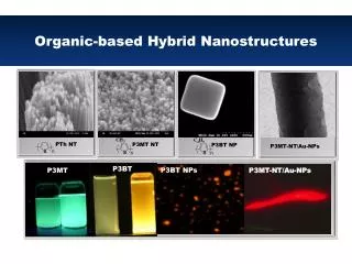
Organic-inorganic hybrids • a new type of materials, which are not present in nature, • synthesized by the sol-gel method. • The organic component can significantly modify the mechanical properties of the inorganic component. • The organic and inorganic components can interpenetrate each other on a nanometer scale. • Depending on the interaction between organic and inorganic components, hybrids are divided into two classes: • (1) hybrids consisting of organic molecules, oligomers or low molecular weight polymers embedded in an inorganic matrix to which they are held by weak hydrogen bond or van der Waals force and • (2) in those, the organic and inorganic components are bonded to each other by strong covalent or partially covalent chemical bonds. • The porosity can also be controlled as well as the hydrophilic and hydrophobic balance. Hybrids with new optical or electrical properties can be tailored. Some hybrids can display new electrochemical reactions as well as special chemical or biochemical reactivity.