Download
1 / 27
270 likes | 420 Vues
This comprehensive guide explores the intricacies of developing sensor-based systems for variable rate application (VRA) in precision agriculture. Learn to recognize essential design details often overlooked and how these details influence the overall system performance. Discover the role of both active and passive sensors, the importance of soil characteristics, and the impact of sensor readings stability. Additionally, understand the decision-making algorithms and communication methods critical for selecting VRA controllers and decision modules. This resource is invaluable for agricultural engineers and IT specialists in enhancing precision farming practices.

E N D
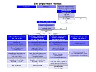
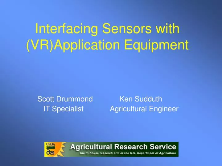
Interfacing Sensors with (VR)Application Equipment Scott Drummond Ken Sudduth IT Specialist Agricultural Engineer
Objectives • Understand the “big picture” of developing a sensor based system for VRA of N. • Recognize design details that often get ignored or at least “underappreciated”. • See how these details affect the design and development of one such research system.
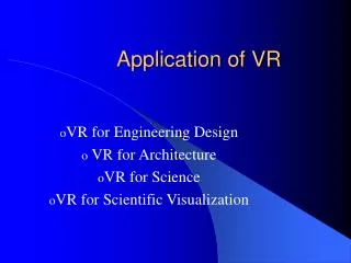
Crop Sensing • Remote sensing • Satellite based • Aerial based • Real time sensing • Passive Sensors • Active Sensors
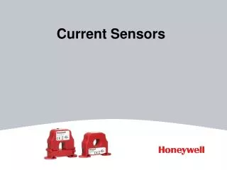
Active Sensors • By using an internal light source, these sensors eliminate problems with sun angle and cloud variations • GreenSeeker by NTech • Crop Circle by Holland Scientific • CropSpec by Topcon
Effect of soil on active sensors? V7 corn with 0 N
Is soil an important part of the signal?Do we need to consider a way to remove the effect of soil?What happens when the soil “color” varies across time or across the landscape?
Stability of sensor readings? Courtesy: Dr. Peter Scharf
Variable Rate Controllers • Things you must consider when selecting the controller for your VRA system… • VRA control type • Range of rates • Response time • Precision and accuracy • Communication method(s)
Variable Rate Controllers • Many systems claim VRA control but… • Real time control • Message based • Controller includes decision module • Map based control • Useful for image based methods – much less attractive for active sensor applications
Variable Rate Controllers • Range of rates for: • Dry fertilizers • Range generally not an issue • Liquid fertilizers • Standard pressure regulated • Capstan spray system (PWM) • SprayTarget variable flow nozzles
Variable Rate Controllers What COULD happen IF our response time was too slow?
Variable Rate Controllers • Communication issues • Serial (RS-232/RS-422/RS-485) • CAN Bus • As applied maps – stored where/how? • Message formats can be open or proprietary
Decision Module • Things to consider when selecting the decision module for your VRA system… • Communication • Algorithm(s) • Flexibility
Decision Module • Questions to ask yourself… • How many algorithms are available? • Is my algorithm “stable”? • Can I adjust (timing/layout/parameters)? • What happens when a new piece of information (sensor/map) appears?
Designing a VRA System • Now that we have an idea of some of the questions to ask… let’s look into the design of a system based upon a set of requirements. • This system was designed for research applications, and may have more stringent requirements than some.
Requirements • Use existing Spra-Coupe • Plot sizes down to 5x10 m in size • Range = 0-210 lb/a N • Precision = 30 lb/a • Accuracy < 5% of full scale. • Map based and sensor based VRA needed • GS & CC sensor data collected and/or used • Algorithm – complete flexibility needed
Application System • Used existing AGCO Fieldstar controller in the SpraCoupe to change system operating pressure to compensate for changes in ground speed. • To get fast response, we chose a “bypass” or 3-way valve system. • When a particular valve (1x, 2x, or 4x) was not sending N to the ground, that same volume of flow was returned to the sprayer tank through a matched orifice. • The pump was always putting out the same volume at the same pressure, and the pressure control system did not have to respond (at least theoretically).
Application System • We chose a 6-row system for reasonable plot widths • Near maximum capacity of the SpraCoupe pump at normal operating speeds • Drop nozzles with 1x, 2x, and 4x orifice plates were installed in row middles • Nominal application rates: • 1x = 30 lb N/acre • 2x = 60 3x = 90 • 4x = 120 5x = 150 • 6x = 180 7x = 210
Data Flow Prior to Application Green GreenSeeker 1 Green GreenSeeker 2 Crop Circle 3 Crop Circle 4 Collect Reference Strip Data Select and/or Combine Sensor Outputs Interpolate/ extrapolate whole-field reference map Get Reference Value at Current Point Spatial or time-base filtering Solenoid Valve Control N Recommendation Algorithm Smoothing, Deadband, Hysteresis Get Current GPS data Decision Module 0, 1x, 2x, 3x, 4x, 5x, 6x, or 7x
a b Drop Nozzles N Sensors Finding the target sensor data… Given that: Sensor data buffered at 10 Hz v = GPS velocity (m/s) a+b = dist from sensors to drops (m) L = system latency (s) The target sensor data was taken this many readings ago… t = 10*(((a+b)/v)+L) In practice, we have averaged 1s of data (10 values per sensor) centered around this target point.
Positioning details… a b Drop Nozzles N Sensors c Sensor Boom Location esens = cos(90-h)*a+egps nsens = sin(90-h)*a+ngps Application Boom Center eboom = cos(90-h)*b+egps nboom = sin(90-h)*b+ngps d Individual Sensor Locations eright = cos(90-(h+atn(c/a))*sqrt(c2+a2)+egps nright = sin(90-(h+atn(c/a))*sqrt(c2+a2)+ngps eleft = cos(90-(h-atn(d/a))*sqrt(d2+a2)+egps nleft = sin(90-(h-atn(d/a))*sqrt(d2+a2)+ngps GPS Antenna Gives Easting(x), Northing(y), h(eading) and v(elocity)
Software Control Loop… Collect store and buffer data: sensors, GPS, psi, status, etc. Find Target Data Find N-Ref Data Calc Raw N-Rate Time >1s? N-Rate < MIN? Yes Yes N-Rate = MIN No No N-Rate > MAX? Yes N-Rate = MAX No Map to 0X-7X Beyond Deadband? Yes Send New Rate To Controller No
How Well Did it Work ? • Accuracy and consistency of response