The muon Drift Tubes pulsing scheme
140 likes | 261 Vues
This document outlines the calibration and operational procedures for the Muon Drift Tubes (DT) used in particle physics experiments, focusing on the pulsing scheme proposed by Roberto Cirio at CERN. It discusses the necessity of pulsing to simulate tracks in single chambers, test installation setups, assess Front End (FE) response, and monitor readout and synchronization. Additionally, the report details chamber configurations, control systems, and strategies for data acquisition without interrupting ongoing experiments, providing insights into efficient detector operations.

The muon Drift Tubes pulsing scheme
E N D
Presentation Transcript
The muon Drift Tubes pulsing scheme Roberto Cirio CERN, march 8 2001 Calibration Working Group meeting
Why pulsing DTs ? • Simulate tracks on a single chamber • Test setup during installation • Test Front End response • Special runs • Monitor readout and trigger synchronization • Abort gap R.Cirio - DT pulsing scheme
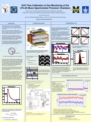
The muon drift tubes • Each of the 60 sectors (4 chambers): • sends data to one channel of the DDU • Each chamber (<1024 channel): • 8 layers of Rf wires connected to FE_boards and RO_boards • is controlled by one Control Board • preamplifier input can receive a test pulse R.Cirio - DT pulsing scheme
FE_board FE_board FE_board FE_board FE_board FE_board CONTROL board RO_board RO_board RO_board Test Pulse Left/Right Test Pulse 1 Test Pulse 2 On-chamber control network TTC signals From TTC On-chamber minicrate Chamber R.Cirio - DT pulsing scheme
Detector Control System Slow Control Master CONTROL Board RS485-optical links Loading pattern sequences on Control Boards • Patterns are loaded on the Control Board and Readout board registers via slow control • Feedback can be given to Run Control via the Detector Control System • Patterns can be loaded without stopping data taking R.Cirio - DT pulsing scheme
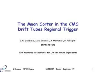
1 15 8 1 2 7 8 7 2 16 15 16 9 9 13 13 61 61 63 63 10 10 14 14 62 62 64 64 Superlayer 1 EN_1 EN_2 EN_3 EN_4 EN_16 Superlayer 2 11 6 12 5 3 4 5 6 12 3 4 11 Pulsing a DT chamber: cells 1,2,3,4 R.Cirio - DT pulsing scheme
Pulsing a DT chamber: cells 1,2,3,4 • Activate: • Enable_1 • Yellow cells and blue cells (Test Pulse Left/Right) • Delay_1-2 (Test Pulse 1) and delay_3-4 (Test Pulse 2) are set (<400 ns) R.Cirio - DT pulsing scheme
1 15 8 1 2 7 8 7 2 16 15 16 9 9 13 13 61 61 63 63 10 10 14 14 62 62 64 64 Superlayer 1 EN_1 EN_2 EN_3 EN_4 EN_16 Superlayer 2 11 6 12 5 3 4 5 6 12 3 4 11 Pulsing a DT chamber:cells 3,4,5,6 R.Cirio - DT pulsing scheme
Pulsing a DT chamber:cells 3,4,5,6 • Activate: • Enable_1 and Enable_2 • Blue cells (Test Pulse Left/Right) • Delay_5-6 (Test Pulse 1) and delay_3-4 (Test Pulse 2) are set (<400 ns) R.Cirio - DT pulsing scheme
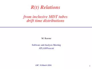
1 15 8 1 2 7 8 7 2 16 15 16 9 9 13 13 61 61 63 63 10 10 14 14 62 62 64 64 Superlayer 1 EN_1 EN_2 EN_3 EN_4 EN_16 Superlayer 2 11 6 12 5 3 4 5 6 12 3 4 11 Pulsing a DT chamber: cells 5,6,7,8 R.Cirio - DT pulsing scheme
Pulsing a DT chamber: cells 5,6,7,8 • Activate: • Enable_2 • Blue cells and yellow cells (Test Pulse Left/Right) • Delay_5-6 (Test Pulse 1) and delay_7-8 (Test Pulse 2) are set (<400 ns) R.Cirio - DT pulsing scheme
Sequence of control signals • RO_boards and Control_Board get the sequence of patterns • TTC sends the Test Pulse Preset • Control Board generates • Test Pulse Advance: load next pattern • Test Pulse Inject: pulse chamber • Test Pulse Reset: go to readout mode • TTC sends LV1A R.Cirio - DT pulsing scheme
CB: TP 1 CB: TP 2 CB: TP Reset TTC: LV1A Control signals: timing diagram TTC Test Pulse (TP) Preset Control Board (CB):TP Advance <400 ns Window for TDC readout equal to trigger latency R.Cirio - DT pulsing scheme
Data volume • Depending on chamber size, 4 to 8 tracks are generated • In each sector, 1 out of 4 chambers will be pulsed • Maximum data volume is equivalent to 2 tracks per sector R.Cirio - DT pulsing scheme