R esistor
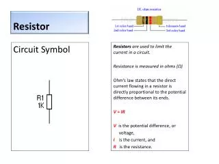
R esistor. Resistors are used to limit the current in a circuit. Resistance is measured in ohms ( Ω ) Ohm’s law states that the direct current flowing in a resistor is directly proportional to the potential difference between its ends . V = IR V is the potential difference, or

R esistor
E N D
Presentation Transcript
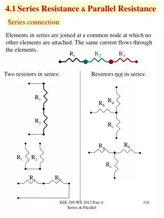
Resistor Resistors are used to limit the current in a circuit. Resistance is measured in ohms (Ω) Ohm’s law states that the direct current flowing in a resistor is directly proportional to the potential difference between its ends. V = IR V is the potential difference, or voltage, I is the current, and R is the resistance. Circuit Symbol
Capacitor The capacitor is a component which is used to store electric charge. The amount of electric charge that a capacitor can hold depends on its capacitance. This is measured in Farads (F). Small capacitors are able to withstand high voltages, and they can be connected either way round. Large ‘electrolytic’ capacitors can only withstand small voltages, and they must be connected with the positive lead to the positive side of the circuit and the negative lead to the negative side. Circuit Symbol Small capacitor Large ‘electrolytic’ capacitor
Capacitors Total of capacitors in series …. etc Total of capacitors in parallel CT = C1 + C2 + C3 …. etc
Light dependent resistor (LDR) Circuit Symbol A light-dependent resistor is a type of resistor that decreases in resistance when it is exposed to light. Also known as a photoresistor.
Thermistor Circuit Symbol A thermistoris simply an electrical resistor whose resistance changes with temperature. Commonly the resistance falls exponentially with increasing temperature and such devices are said to have a negative temperature coefficient (NTC).
Diode Circuit Symbol A diode is a component that allows current to flow in one direction only. Diodes are normally used to prevent damage to other polarised components in circuits: e.g. a diode can protect against current flowing the wrong way if the battery is put in back to front. anode cathode anode cathode
Zener diode Circuit Symbol A zenerdiode is a diode which allows current to flow in the forward direction in the same manner as an ideal diode, but will also permit it to flow in the reverse direction when the voltage is above a certain value known as the breakdown voltage. anode cathode anode cathode
Light Emitting Diode(LED) Circuit Symbol AnLED, or Light Emitting Diode, is an electronic device that emits light when an electrical current is passed through it.
Transistors Circuit Symbol Transistors are electronic component used in circuits to control large amounts of current with a small amount current.
Operational amplifier (Op Amp) Circuit Symbol An operational amplifier (op-amp) is a high-gain electronic voltageamplifierwith a differential input and an output. An op-amp produces an output voltage that is typically hundreds of thousands of times larger than the voltage difference between its input terminals.
555 timer IC Circuit Symbol The 555 timer IC is an integrated circuit (chip) used in a variety of timer, pulse generation, and oscillator applications. The 555 can be used to provide time delays, as an oscillator, and as a flip-flop element.
Other circuit symbols Loudspeaker Switch Ammeter Buzzer Voltmeter Microphone
Wires crossing Circuit Symbol Wires connected together Wire junction Circuit Symbol Wires crossing no connection
Battery Circuit Symbol
Bulb Circuit Symbol Bulb holder
Breadboard Breadboards are used to construct and test circuits. Wires and components are simply pushed into the holes to form a completed circuit and power can be applied. One of the main advantages of using a breadboard is that the components are not soldered and if they are positioned incorrectly they can be moved easily to a new position on the board.