Congestion Control
Congestion Control. Class 18 Resource Allocation Considerations. Issues and Principles Causes of Congestion Approaches to Congestion Control. Congestion Control. Resource Allocation Process by which NEs try to meet competing demands from the same network resources:

Congestion Control
E N D
Presentation Transcript
Congestion Control Class 18 Resource Allocation Considerations CSE 5344/7344
Issues and Principles Causes of Congestion Approaches to Congestion Control Congestion Control CSE 5344/7344
Resource Allocation Process by which NEs try to meet competing demands from the same network resources: Bandwidth + buffer space Congestion Control Efforts made by NEs to prevent or respond to overload conditions in the NW Could demand certain NEs to stopTXing Prefer a notion of fairness Terminology CSE 5344/7344
Source 1 10-Mbps Ethernet Router Destination 1.5-Mbps T1 link 100-Mbps FDDI Source 2 Issues – Congestion on Switched NWs • Two sides of the same coin • pre-allocate resources so at to avoid congestion • control congestion if (and when) is occurs • Two points of implementation • hosts at the edges of the network (transport protocol) • routers inside the network (queuing discipline) • Underlying service model • best-effort (assume for now) • multiple qualities of service (later) • soft-state versus hard-state flow information Lots of capacity on immediate links Reduced capacity on NW links “Default Router” – the bottleneck CSE 5344/7344
Source 1 Router Destination 1 Router Source 2 Router Destination 2 Source 3 Framework Channels – process-to-process • Taxonomy • router-centric versus host-centric • reservation-based versus feedback-based • Implicit (behavioral) vs. explicit feedback • window-based versus rate-based Data “flows” – visible to routers inside the network CSE 5344/7344
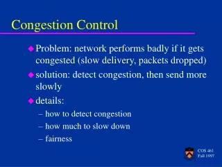
Congestion: informally: “too many sources sending too much data too fast for network to handle” different from flow control manifestations: lost packets (buffer overflow at routers) long delays (queueing in router buffers) Principles of Congestion Control CSE 5344/7344
packet loss knee cliff Throughput congestion collapse Load Delay Load Congestion: A Close-up View • knee – point after which • throughput increases very slowly • delay increases fast • cliff – point after which • throughput starts to decrease very fast to zero (congestion collapse) • delay approaches infinity CSE 5344/7344
knee cliff Throughput congestion collapse Load Congestion Control vs. Congestion Avoidance • Congestion control goal • stay left of cliff • Congestion avoidance goal • stay left of knee • Right of cliff: • Congestion collapse CSE 5344/7344
Congestion Collapse: How Bad is It? • Definition: Increase in network load that results in a decrease of useful work done • Many possible causes • Spurious retransmissions of packets still in flight • Undelivered packets • Packets consume resources and are dropped elsewhere in network • Fragments • Mismatch of transmission and retransmission units • Control traffic • Large percentage of traffic is for control • Stale or unwanted packets • Packets that are delayed on long queues CSE 5344/7344
Throughput/delay Delay Throughput Optimal Load load Evaluation Criteria for Resource Allocation Scheme Effectiveness • Fairness • Power (ratio of throughput to delay) CSE 5344/7344
Causes of Congestion CSE 5344/7344
two senders, two receivers one router, infinite buffers no retransmission large delays when congested maximum achievable throughput lout lin : original data unlimited shared output link buffers Host A Host B Causes/costs of congestion: scenario 1 Per-connection throughput C= Router Capacity Aggregate throughput = C is bad for delay CSE 5344/7344
one router, finite buffers sender retransmission of lost packet Rate of sending original data + retransmissions offered load lin: original data Host A lout l'in : original data, plus retransmitted data Host B finite shared output link buffers Causes/costs of congestion: scenario 2 l'in CSE 5344/7344
always: (goodput) “perfect” retransmission only when loss: retransmission of delayed (not lost) packet makes larger (than perfect case) for same l l l > = l l l in in in out out out C/4 Causes/costs of congestion: scenario 2 Retransmissions due to loss Retransmissions due to queue delay No Loss case “costs” of congestion: • more work (retrans) for given “goodput” • unneeded retransmissions: link carries multiple copies of pkt CSE 5344/7344
four senders multihop paths timeout/retransmit l l in in lout lin: original data Host B l'in: original data, plus retransmitted data finite shared output link buffers R1 R4 HostC R2 R3 Host D Host A Causes/costs of congestion scenario 3 Q:what happens as and increase ? Max R2 Capacity = C If l'in is very large, arrival rate at R2 can overwhelm R2 As offered load infinity, B-D traffic supersedes A-C traffic to zero CSE 5344/7344
lout Host A Host B Causes/costs of congestion: scenario 3 Throughput Offered Load Multi-hop flows vs. single-hop flows fair? Another “cost” of congestion: • when packet dropped, any “upstream transmission capacity” used for that packet is wasted • NW is better off if R1 discarded packets • NW is better off if R2 preferentially transmitted packets that already crossed the network CSE 5344/7344
Resource Allocation Schemes CSE 5344/7344
Queuing Discipline • First-In-First-Out (FIFO) • does not discriminate between traffic sources (flows) • Tail-drop – is a drop policy (not a scheduling method) • Pushes congestion control / resource allocation responsibility out to the hosts CSE 5344/7344
Queuing Discipline • FIFO with Priority Queuing (FIFO-PQ) • Multiple FIFO queues at each router • Differential (TOS-based) drops • Lets VIP jump to head of the line • Problem? • Can “starve-out” lower-priority packets • Needs a means to force those packets out as well CSE 5344/7344
Queuing Discipline • Fair Queuing (FQ) • explicitly segregates traffic based on flows • ensures no flow captures more than its share of capacity • punishes non-conforming flows • variation: weighted fair queuing (WFQ) • still needs an end-to-end congestion control mechanism • Problem? Different Packet lengths Algorithm “views transmission” as bit-by-bit CSE 5344/7344
FQ Algorithm – single flow • Suppose clock ticks each time a bit is transmitted • Let Pi denote the length of packet i • Let Si denote the time when start to transmit packet i • Let Fi denote the time when finish transmitting packet i • Fi = Si + Pi • When does router start transmitting packet i? • if before router finished tx packet i - 1 from this flow, then tx immediately after last bit of i - 1 (Fi-1) • if no current packets for this flow, then start transmitting when arrives (call this Ai) • Thus: Fi = MAX (Fi - 1, Ai) + Pi CSE 5344/7344
Flow 1 Flow 2 Flow 1 Flow 2 Output (arriving) (transmitting) Output F = 10 F = 10 F = 8 F = 5 F = 2 (a) (b) FQ Algorithm – multiple flows • For multiple flows • calculate Fi for each packet that arrives on each flow • treat all Fi’s as timestamps • next packet to transmit is one with lowest timestamp • The one that should finish before the others based on time • Not perfect: can’t preempt current packet • So not a perfect case of bit-by-bit round robin • Example Select F5,F8 before F10 F2 is smaller and finished before F10, if true bit-by-bit round robin CSE 5344/7344
FQ Algorithm – multiple flows • Link is never left idle – work conserving • Active NE can use full link capacity • One flow cannot use more than 1/n capactiy if have n flows • Provides a guaranteed minimum shared bandwidth is provided each flow • Weighted Fair Queuing • Specifies (weighs) how much bandwidth any flow receives • FQ, weight = 1 for each flow • Mechanism can provide TOS General system concept separate Mechanism from Policy CSE 5344/7344
Approaches to Congestion Control CSE 5344/7344
End-end congestion control: no explicit feedback from network To Transport Layer congestion inferred from end-system observed loss, delay approach taken by TCP Since IP does not provide any feedback Network-assisted congestion control: routers (network-layer components) provide feedback to end systems Feedback may be: single bit indicating congestion (SNA, DECnet, ATM-ABR) a router tells the sender the explicit rate to transmit on a link Approaches towards congestion control Two broad approaches towards congestion control: CSE 5344/7344
ABR: available bit rate: “elastic service” if sender’s path “under-loaded”: sender should use available bandwidth if sender’s path congested: sender throttled to minimum guaranteed rate RM (resource management) cells: sent by sender, interspersed with data cells bits in RM cell set by switches (“network-assisted”) RM cells returned to sender by receiver, with bits intact Network-assisted Congestion Control:ATM ABR CSE 5344/7344
ABR Congestion Control is a rate-based approach: Sender computes a maximum rate at which it can send Sender regulates transmissions accordingly Three mechanisms to signal congestion-related info: bits in RM cell set by switches (“network-assisted”) RM cells are interspersed with data cells (1:32 default) NI bit: no increase in rate (mild congestion) – bit = 1 CI bit: congestion indication – bit = 1 Switches set these bits as RM cells arrive ATM ABR Congestion Control CSE 5344/7344
Three mechanisms to signal congestion-related info: ER Setting – Explicit Rate Each RM cell also contains a two-byte ER field Congested switch lowers the value contained in the ER field of a passing RM cell This sets the minimum rate is across all src<>dst switches EFCI bit – Explicit Forward Congestion Indication Each data cell contains an EFCI bit Switch sets EFCI bit = 1 to inform destination host Destination sets CI bit = 1 in RM cell to source host ATM ABR Congestion Control ATM ABR source adjusts sending rate as a function of CI, NI, ER values CSE 5344/7344
End-to-End Congestion Control CSE 5344/7344
TCP Congestion Control • Idea • assumes best-effort network (FIFO or FQ routers) each source determines network capacity for itself • uses implicit feedback • the ACKs pace transmission (self-clocking) • Challenge • determining the available capacity in the first place • adjusting to changes in the available capacity CSE 5344/7344
Additive Increase/Multiplicative Decrease (AIMD) Objective: adjust to changes in the available capacity • New state variable per connection: CongestionWindow • limits how much data source has in transit • NW congestion counterpart of flow-control AdvertisedWindow MaxWin = MIN(CongestionWindow,AdvertisedWindow) EffWin = MaxWin - (LastByteSent - LastByteAcked) • Idea: • increaseCongestionWindow when congestion goes down • decreaseCongestionWindow when congestion goes up CSE 5344/7344
How does sender perceive congestion? loss event = timeout or 3 duplicate ACKs TCP sender reduces rate (CongWin) after loss event three mechanisms to adjust: AIMD slow start conservative after timeout events TCP Congestion Control CSE 5344/7344
AIMD (cont’d) Question: how does the source determine whether or not the network is congested? • Answer: a timeout occurs • timeout signals that a packet was lost • packets are seldom lost due to transmission error • lost packet implies congestion • Behaviorally based CSE 5344/7344
Source Destination … AIMD (cont) • In practice: increment a little for each ACK Increment = MSS * (MSS/CongestionWindow) CongestionWindow += Increment • Algorithm • increment CongestionWindow by one packet per RTT (linear increase) • divide CongestionWindow by two whenever a timeout occurs (multiplicative decrease) CSE 5344/7344
multiplicative decrease: cut CongWin in half after loss event Long-lived TCP connection TCP AIMD additive increase: increase CongWin by 1 MSS every RTT in the absence of loss events: probing AIMD is necessary for a stability Decrease aggressively / increase conservatively consequences are less for a smaller window than a larger window CSE 5344/7344
When connection begins, CongWin = 1 MSS Example: MSS = 500 bytes & RTT = 200 msec initial rate = 20 kbps available bandwidth may be >> MSS/RTT desirable to quickly ramp up to respectable rate TCP Slow Start • When connection begins, increase rate exponentially fast until first loss event CSE 5344/7344
When connection begins, increase rate exponentially until first loss event: double CongWin every RTT done by incrementing CongWin for every ACK received Summary: initial rate is slow but ramps up exponentially fast Host A Host B one segment RTT two segments four segments time TCP Slow Start (more) CSE 5344/7344
Slow Start (cont’d) • Exponential growth, but slower than all at once • Used… • when first starting connection • when connection goes dead waiting for timeout CSE 5344/7344
Summary: TCP Congestion Control • When CongWin is belowThreshold, sender in slow-start phase, window grows exponentially • When CongWin is aboveThreshold, sender is in congestion-avoidance phase, window grows linearly • When a triple duplicate ACK occurs, Threshold set to CongWin/2 and CongWin set to Threshold • When timeout occurs, Threshold set to CongWin/2 and CongWin is set to 1 MSS. CSE 5344/7344
TCP sender congestion control CSE 5344/7344
End of Class 18 CSE 5344/7344