Mechatronic Motors
410 likes | 604 Vues
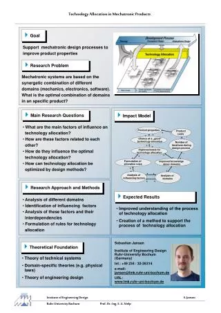
Mechatronic Motors. Mechatronics - energiflow. Structures of the energy conversion system ( < 1 h) Primary energy to output Electrical as intermediate Power electronic converters as components ( < 3 h) AC/DC/AC Modulation Power Units (50 Hz / SMPS / Integration)

Mechatronic Motors
E N D
Presentation Transcript
Mechatronics - energiflow Structures of the energy conversion system (< 1 h) Primary energy to output Electrical as intermediate Power electronic converters as components (< 3 h) AC/DC/AC Modulation Power Units (50 Hz / SMPS / Integration) Passive components / Integration of passives Electromechanical converters as components (< 3 h) Conv. machine types Elektrostrictive/magnetostrictive converters Cooling Power and Energy density Energyconvertsre as construction elements (< 1 h) Laminated steel / powder pressing / injection moulding Powerelectronic measurements (< 2 h) Current / voltage / flux Torque /speed / position Preassure / flow (in pumps)
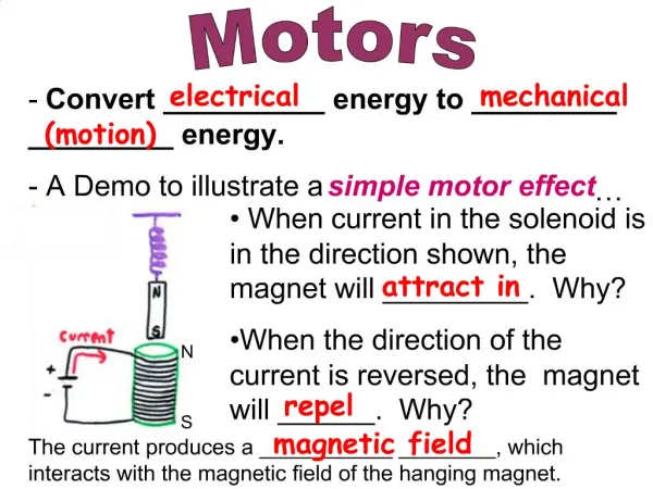
Off the shelf, or tailor made? • Off the shelf – complete machine with bearings, housing etc. • This machine is normally connected to the load via a coupling • Tailor made • Can be made an integrated part of the driven object. • Iron core material can be doubly utilized, magnetic conductor and mechanical design element.
Background Control software Power Electronics Gear box Driven object Coupling El. Motor Coupling • Most mechanical designs use actuators • System designs are adapted for “off the shelf”-actuators
Integrated designs Control software Power Electronics Gear box Driven object Coupling El. Motor Coupling • Integration of actuators requires … • Actuator design knowledge • Production method expertise • … and gives • Smaller size and lower weight • Lower energy consumption • Lower EMC-problems • Lower cost Driven object El. Motor Pow. El Control software
Design task • Choose geometry • Estimate response time and dynamics • Select motor drive • Calculate electrical power need • Design power supply • 20 V / 200 W trafo available
System layout There are at least two design flaw’s at this stage: • A standard transformer is used, should be eliminated in the power supply, but is kept for simplification in the power supply design. • A gear box may not be the best solution, and any alternative drive has not been investigated yet.
Power requirements • To design the power supply, we need to know the maximum power requirements. • These come from the drive power and the control electronics power consumption. • The drive power results from • the mechanical work in normal operation • the additional work related to speed changes • Losses in the gear, motor and power electronics • To evaluate the drive power, a drive system model in dynamic simulation is convenient to build, for two reasons: • It will force us to develop the position and speed controllers • It will give us all instantaneous speed and force values to calculate instantaneous mechanical power.
Details of the power supply • Voltage controller • The current reference is scaled with a full wave rectified sinewave in phase with the line voltage but with unity amplitude. • Inductor • Includes a small resistive voltage drop • Capacitor • Ideal • Load current • The load power from the simulation of the mechanical system is use to calculate the load current
Mechanical control loop • NB! We do not model the electrical dynamics at this stage, only the mechanical. Speed reference generator Angular speed controller Pulley and load Linear to angular speed Torque source
Details of the mechanical control loop • Speed reference generation • Shift sign of the speed reference every time it hits an end point • Linear to angular speed • Solve the dynamics in angular speed instead • Angular speed * Radius = Linear speed • Angular speed control • PI-controller • Torque source • Does not respond instantaneously – represent as 1’st orde low pass filter • Has a limited torque capability – insert corresponding limitation • Pulley and load • Estimate equivalent intertia
Standard machines • DC machines • Permanent Magnet • Series, Shunt and Compound wound • AC servo motors • Permanent Magnet • Sinusoidal currents • Reluctance motors • Stepper motors
Electrical Motors properties • High torque density • 1...30 Nm/kg • Compare combustion motors 1...2 Nm/kg • Compare Hydraulmotors 600 Nm/kg • High efficiency • < 98%
Motors Torque and Inertia One rotor conductor (of all along the airgap surface): Total torque along the airgap: Inertia
The Dis2L Output Coefficient • Mechanical power: Essen’s rule Limited by rotational stresses Limited by losses and cooling Proportional to the rotor volume Limited by saturation
Servo motor - definition • Motor for torque, speed or position control • NB! Line start motors and voltage or frequency controlled motors do not qualify as servo motors.
DC motors • Only PM • Mechanical commutation of rotor currents • T=k*ia • Without current feedback risc for over current at start/reversal and permanent magnet demagnetisation • Current feedback protects motor AND load
DC Motor as servo motor • Smaller and smoother rotor • lower inertia and inductance • Shorter torque rise time • Faster acceleration • Skewed rotor • Smoother torque • Built in sensors • Speed • Position
Mathematical model • Rotor circuit • Torque T=ym·ia
DC motor pros and cons. • Established • Soft operation • High efficiency • Cheap • Quiet • Wear • Sparking • EMC
AC servo motors permanent magnetized • Winding in th stator • Electronically commutated • Position sensor needed • High torque density
Stationary operating point Inductive Voltage drop Resistive Voltage drop Induced Voltage
AC servo motor pros and cons. • Magnet material expensive • Small rotor desired – magnets difficult (expensive) to mount • Expensive control electronics • Position sensor • Can pick up iron dust, sealed • Soft operation • High efficiency • Quiet
Induction motor Three phase stator No magnets Short circuit, ”squirrel cage”, rotor Three phase current in the stator The rotor current must be induced Three phase power electronics
AM - dynamik Utgångsläge Flytta statorströmmen snabbt ett steg - vad händer i rotorn?
Induction motor pros and cons • Can start when connected to the public grid • Robust and reliable • Cheap • Simple to maintain • Standardizsed • Efficiency • Power factor
Stepper Motors • Variable Reluctance • Rotor is made of only (soft) iron with no magnets but salient teeth • PM stepper motors • Rotor is made of permanent magnets • Hybrid stepper motors • Rotor has both teeth and permanent magnets
Variable reluctance motor • One winding at a time is energized. • The rotor takes one ”step” at a time
PM stepper motor • The electromagnet of the stator and the permanent magnet of the rotor defines specific positions • By alternating what phase is magnetized, the rotor takes a ”step” at a time
Stepper motor control • Voltage control mode • The current is controller by (pre-)selected voltage – NO CURRENT FEEDBACK • Does not work well at higher speeds • Current control mode • True current feedback is used.
Stepper motor pros and cons • Noise • At high acceleration (dynamic) or static load synchronism may be lost. Results in total loss of torque. • Low torque @ high speed • Cheap • No position feedback (that’s the idea) • Position controlled by counting the number of pulses that is supplied. • High torque @ low speed
Production methods • Traditionally: • Cut, stack and wind • Many production steps, many parts • Today: • Press and wind • Fewer prod steps, fewer parts • Tomorrow • Mould? • Single prod step,1 part
An example of an injection moulded design – in more detail Winding Rotor part Radial fan wheel Circuit board Stator part (on the circuit board)
Why not before? • In a conventional design the result is poor • The magnetic flux travels a rather long distance in iron • Thus, the iron must be a good flux conductor
Torque 4...10 2...3 • Torque = k * Flux density * Air gap radius^2 * Axial length • When introducing a low permeability material in a conventional design, the Flux density drops a factor 4...10. • This leads to low performance • - That’s why no one has considered this before. • But, if we can increase the air gap radius correspondingly, we can regain the torque