Download
1 / 53
590 likes | 1.35k Vues
Energy bands semiconductors. Dr. Md.Shakowat Zaman Sarker Assistant Professor Dept. of EEE International Islamic University Chittagong. Outlines.

E N D
Energy bands semiconductors Dr. Md.Shakowat Zaman Sarker Assistant Professor Dept. of EEE International Islamic University Chittagong
Outlines Energy bands, Metals, Semiconductor and Insulators, Direct and indirect semiconductor, variation of Energy band with alloy composition, Electrons and Holes, Effective mass, intrinsic and Extrinsic Semiconductors, Electrons and Holes and hole in quantum wells
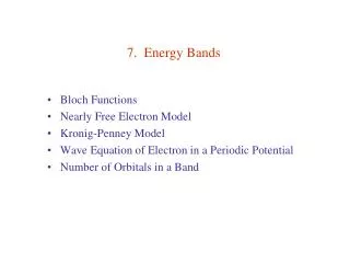
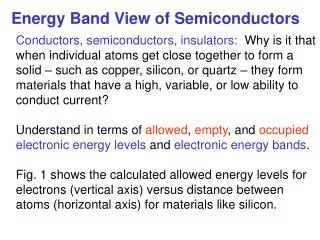
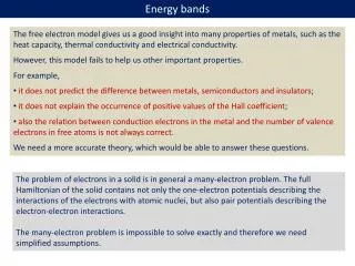
3-1-3. Metals, Semiconductors & Insulators • The difference bet-ween insulators and semiconductor mat-erials lies in the size of the band gap Eg, which is much small-er in semiconductors than in insulators. Empty Empty Eg Eg Filled Filled Insulator Semiconductor
3-1-3. Metals, Semiconductors & Insulators • In metals the bands either overlap or are only partially filled. Thus electrons and empty energy states Overlap Metal are intermixed with-in the bands so that electrons can move freely under the infl-uence of an electric field. Partially Filled Filled Metal
3-2. Carriers in Semiconductors • The semiconductor has filled valance band and empty conduction band at 0K, we must consider the increase in conduction band electrons by thermal excitations across the band gap as temperature is raised. • In addition, after electrons are excited to the conduction band, the empty states left in the valance band can contribute to the conduction process. • Impurities has an important effect on the energy band structure and on the availability of charge carriers
3-2-1. Electrons and Holes • As the temperature of a semiconductor is raised from 0K, some electrons in the valance band receive enough thermal energy to be excited across the band gap to the conduction band. The result is a material with some electrons in an otherwise empty conduction band and some unoccupied states in an otherwise filled valance band. An empty state in a valance band is refer to as hole. If the conduction band electron and the hole are created by the excitation of valance band electron to the conduction band, they are called an electron-hole-pair (EHP)
3-2-1. Electrons and Holes • Hole current is really due to an electron moving in the opposite direction in the valence band. • Electron current is an electron moving from state to state in the conduction band.
3-2. Carriers in Semiconductors Ec Eg 300ºK 18ºK 11ºK 15ºK 14ºK 20ºK 19ºK 13ºK 17ºK 12ºK 16ºK 1ºK 4ºK 2ºK 3ºK 0ºK 10ºK 8ºK 7ºK 6ºK 5ºK 9ºK Ev Electron Hole Pair E P H
3.2.2 Effective mass • Electrons in a crystal are not totally free. • The periodic crystal affects how electrons move through the lattice. • We use and effective mass to modify the mass of an electron in the crystal and then use the E+M equations that describe free electrons.
3.2.2 Effective mass • E • k
3.2.2 Effective mass • The double derivative of E is a constant • Not all semiconductors have a perfectly parabolic band structure • The different atomic spacing in each direction gives rise to different effective masses in different crystal directions. This can be compensated by using an average value of effective mass.
A perfect semiconductor crystal with no impurities or lattice defects is called an Intrinsic semiconductor. In such material there are no charge carriers at 0ºK, since the valence band is filled with electrons and the conduction band is empty. 3-2-3. Intrinsic Material
Eg 3-2-3. Intrinsic Material e- Si h+ n=p=ni
3-2-3. Intrinsic Material • If we denote the generation rate of EHPs as and the recombination rate as equilibrium requires that: • Each of these rates is temperature depe-ndent. For example, increases when the temperature is raised.
3-2-4. Extrinsic Material • In addition to the intrinsic carriers generated thermally, it is possible to create carriers in semiconductors by purposely introducing impurities into the crystal. This process, called doping, is the most common technique for varying the conductivity of semiconductors. • When a crystal is doped such that the equilibrium carrier concentrations n0 and p0 are different from the intrinsic carrier concentration ni , the material is said to be extrinsic.
3-2-4. Extrinsic Material Ec Ed 50ºK 18ºK 20ºK 15ºK 14ºK 11ºK 19ºK 17ºK 13ºK 12ºK 16ºK 1ºK 4ºK 2ºK 3ºK 0ºK 10ºK 8ºK 7ºK 6ºK 5ºK 9ºK Ev Donor
3-2-4. Extrinsic Material Ec 50ºK 18ºK 20ºK 15ºK 14ºK 11ºK 19ºK 17ºK 13ºK 12ºK 16ºK 4ºK 1ºK 2ºK 3ºK 0ºK 10ºK 8ºK 7ºK 6ºK 5ºK 9ºK Ea Ev Acceptor
3-2-4. Extrinsic Material e- Sb h+ Al Si
3-2-4. Extrinsic Material • We can calculate the binding energy by using the Bohr model results, consider-ing the loosely bound electron as ranging about the tightly bound “core” electrons in a hydrogen-like orbit.
3-2-4. Extrinsic Material • Example 3-3: Calculate the approximate donor binding energy for Ge(εr=16, mn*=0.12m0).
3-2-4. Extrinsic Material • Answer: Thus the energy to excite the donor electron from n=1 state to the free state (n=∞) is ≈6meV.
3-2-4. Extrinsic Material • When a ш-Vmaterial is doped with Si or Ge, from column IV, these impurities are called amphoteric. • In Si, the intrinsic carrier concentration ni is about 1010cm-3 at room tempera-ture. If we dope Si with 1015 Sb Atoms/cm3, the conduction electron concentration changes by five order of magnitude.
3-3. Carriers Concentrations • In calculating semiconductor electrical pro-perties and analyzing device behavior, it is often necessary to know the number of charge carriers per cm3 in the material. • The majority carrier concentration is usually obvious in heavily doped material, since one majority carrier is obtained for each impurity atom (for the standard doping impurities). • The minority carriers concentration is not obvious, however, nor is the temperature dependence of the carrier concentration. • To obtain equations for the carrier concentrations we must investigate the distribution of carriers over the available energy states. The distribution function as given:
Donors and Acceptors • Fermi level , Ef • Carrier concentration equations • Donors and acceptors both present
3-3-1. The Fermi Level • Electrons in solids obey Fermi-Dirac statistics. • In the development of this type of statistics: • Indistinguishability of the electrons • Their wave nature • Pauli exclusion principle must be considered. • The distribution of electrons over a range of these statistical arguments is that the distrib-ution of electrons over a range of allowed energy levels at thermal equilibrium is
3-3-1. The Fermi Level • k : Boltzmann’s constant • f(E) : Fermi-Dirac distribution function • Ef : Fermi level
3-3-1. The Fermi Level • An Energy E equal to the fermi level energy EF, the occupation probability is • The Energy state at the fermilevel has a probability of ½ of being occupied by an electron.
f(E) 1 1/2 E Ef Exponent positive: F(E)=1 for E<FE • T=0 Exponent positive: F(E)=0 for E>FE T=0ºK T1>0ºK T2>T1 Fermi-Dirac distribution Function
3-3-1. The Fermi Level • In intrinsic material, the concentration of electron in conduction band and concentration of Hole in valance band is equal. The fermi level FE must lie at the middle of band-gap. • In n-type material, higher concentration of electron in the conduction band compare with hole concentration in valance band. • In p-type material, the FE lie near the valance band
f(Ec) [1-f(Ec)] 3-3-1. The Fermi Level • Fermi distribution function applied to Semiconductor E f(Ec) Ec Ef Ev ≈ ≈ f(E) Intrinsic p-type n-type 1 0 1/2
Ef 3-3-2. Electron and Hole Concentrations at Equilibrium E Electrons N(E)f(E) EC EV N(E)[1-f(E)] Holes Intrinsic n-type p-type
3-3-2. Electron and Hole Concentrations at Equilibrium The concentration of electrons in the conduction band is • N(E)dE : is the density of states (cm-3) in the energy range dE. • O: Electron and Hole concentration symbol in equilibrium condition. • dE: N# of Electron per unit volume in energy range • N(E): Can be calculate by quantum mechanics
3-3-2. Electron and Hole Concentrations at Equilibrium • The result of the integration is the same as that obtained if we repres-ent all of the distributed electron states in the conduction band edge EC. The conduction band Electron concentration is simply the effective density of states at Ec times of probability of occupancy at Ec
3-3-2. Electron and Hole Concentrations at Equilibrium Fermi function can be simplified as Concentration of Electron in conduction band The Effective density of states Nc
3-3-2. Electron and Hole Concentrations at Equilibrium Similar argument, the concentration of holes
3-3-2. Electron and Hole Concentrations at Equilibrium The electron and hole concentrations are valid whether the material is intrinsic or doped, provided thermal equilibrium is maintained. Thus for intrinsic material, lies at some intrinsic level Ei near the middle of band gap, and the intrinsic electron and hole concentration are:
3-3-2. Electron and Hole Concentrations at Equilibrium The product of no and po at equilibrium is a constant for a particular material and temperature, even is doping is varied:
3-3-2. Electron and Hole Concentrations at Equilibrium The intrinsic electron and hole concentration are equal, ni=pi; thus the intrinsic concentration is The product of electron and hole concentration
3-3-2. Electron and Hole Concentrations at Equilibrium • Example 3-4: A Si sample is doped with 1017 As Atom/cm3. What is the equilibrium hole concentra-tion p0 at 300°K? Where is EF relative to Ei?
3-3-2. Electron and Hole Concentrations at Equilibrium • Answer: Since Nd»ni, we can approximate n0=Nd and
3-3-2. Electron and Hole Concentrations at Equilibrium • Answer (Continue) : Ec EF 0.407eV Ei 1.1eV Ev
4.3 Carrier lifetime and photo-conductivity Direct recombination of Electrons and hole • Electron drops from conduction band to the valence band and recombines with a hole without any change in momentum (E vs K) . • The energy difference is used up in an emitted photon. • This process occurs at a certain rate in the form of how long does a free electron or hole remain free before it recombines (tn or tp)
4.3 Carrier lifetime and photo-conductivity • Direct recombination of Electrons and hole • tn or tp are dependant on doping level, crystal quality and temperature. • Indirect recombination; Trapping • The probability of a direct recombination is small in Si and Ge. • A trapping level is needed. No photons generated just phonons (lattice vibrations) • Minority carrier lifetime dominates recombination process.
4.3 Carrier lifetime and photo-conductivity • The Fermi level (EF) is only meaningful at thermal equilibrium. • Under excitation we use the quasi Fermi level to denote excess hole and electron concentrations.
4.4 Diffusion of carriers • Diffusion process • The random motion of similar particles from a volume with high particle density to volumes with lower particle density • A gradient in the doping level will cause electron or hole flow, which causes an electric field to build up until the force from the gradient equals the force of the electric field. • no current will flow at equilibrium
4.4Diffusion of carriers • Diffusion process • t is the mean free time that 1/2 of the particle will enter the next dx segment. • l is the mean free path of a particle between collisions.
4.4 Diffusion and drift of carriers • Drift diffusion equations • The hole drift and diffusion current densities are in the same direction. • The electron drift and diffusion current densities are in the opposite direction.
4.4 Diffusion and drift of carriers • Drift diffusion equations • Minority current flow is primarily diffusion. • Majority current flow is primarily drift. • An applied electric field will cause a positive slope in Ei (Ev and Ec as well) • This can be used to derive the Einstein relation.