Download

1 / 33
350 likes | 497 Vues
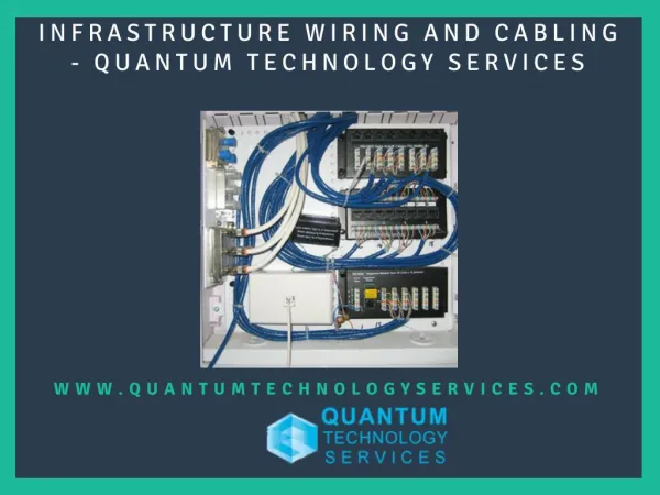
Explore the fundamentals of cabling technology and network standards essential for effective data communication between remote systems. Discover the various types of networks such as LAN and WAN, their topologies (bus, ring, star), and necessary components including hubs, switches, and routers. Learn about key standards and abbreviations, including ANSI/TIA/EIA and ISO/IEC guidelines that ensure reliable and efficient data transfer. This comprehensive overview is designed for those seeking to enhance their knowledge in network infrastructures and communication standards.

E N D
Networks • Data Communication • Transfer of digital data between between 2 or more remotely attached autonomous systems in a reliable and understandable manner
Networks • Network – data communication between 2 or more devices with the ability to access shared resources • LAN - local area network • WAN - wide area network
Networks Topologies Bus Ring Star
Networks Components • Hubs • Switches • Routers
Networks Components (Cont.) Hub connects multiple devices on same network via individual dedicated cable runs (star topology) Switch provides a dedicated communication channel between network devices
Networks Components (Cont.) • Router connects between entities residing on different networks
Common Abbreviations ACR - Attenuation to Cross-Talk Ratio P.ACR - Power Sum Attenuation to Cross-Talk Ratio BER - Bit Error Rate FEXT - Far End Cross-Talk NEXT - Near End Cross-Talk P.S. NEXT - Power Sum Near End Cross-Talk ELFEXT - Equal Level Far End Cross-Talk P.S. ELFEXT - Power Sum Equal Level Far End Cross-Talk STP - Shielded Twisted Pair TSB - Telecommunications Systems Bulletin UTP - Unshielded Twisted Pair Alien XT - Alien Cross Talk
Standards Organizations • EIA/TIA (USA) • Electrical/Telecommunication Industries Association • ANSI • American National Standards Institute • ISO/IEC • International Organization for Standardization • International Electrotechnical Commission • CENELC • European Committee for Electrotechnical Standardization • IEEE • Institute of Electrical and Electronic Engineers
World Structured Cabling Standards • ANSI/TIA/EIA-568-B.1 and B.2ratified in 2001, CAT5 / CAT5E • ANSI/TIA/EIA-568-B.2-1ratified in 2002, CAT6 • ANSI/TIA/EIA-568-B.2-10 finalized May 2008, CAT6a • ISO/IEC 2nd edition generic cabling standard 11801 ratified in 2002 • CENELEC generic cabling standard EN 50173-1ratified in 2002
Standards HistoryANSI / TIA / EIA-568 • ANSI/EIA/TIA 568 published in 1991 The 1st Commercial Building Telecommunications Wiring Standard The original document, together with TSB-36 & TSB-40 specified the basic transmission requirements of Category 3, 4 & 5 • ANSI/EIA/TIA 568A published in 1995Recognized Cables for Horizontal Cabling: 4 pair 100 UTP cables (including S/UTP) 2 pair 150 STP cables (IBM TYPE-1A) 2 fiber 62.5/125µ and 50/125µ fiber-optic cable
ANSI/TIA/EIA-568-B series • ANSI/TIA/EIA-568-B.1General Infrastructure requirements Copper and Fiber • ANSI/TIA/EIA-568-B.2Copper requirements Cat3, Cat5, Cat5E • ANSI/TIA/EIA-568-B.3Fiber requirements
ANSI/TIA/EIA-568-B-1 seriesGeneral Requirements • B-1.1 Minimum 4 pair UTP and ScTP patch cable bend radius • B-1.2 Bonding and Grounding • B-1.3 Supportable distances and Channel Attenuation for F/O applications by Fiber type • B-1.4 Recognition of CAT6 and 850 nm Laser-Optimized 50/125 µm MM F/O cabling • B-1.5 Cabling for Telecommunication Enclosures • B-1.6 PoE (Power Over Ethernet) • B-1.7 F/O connectivity Methods for Polarity
ANSI/TIA/EIA-568-B-2 seriesCopper • B-2.1 Category 6 specifications • B-2.2 Balanced Twisted-Pair Cabling Components • B-2.3 IL & RL Pass/Fail Determination • B-2.4 Solderless Connection Reliability Requirements for Copper Connecting Hardware • B-2.5 Corrections to TIA/EIA-568-B.2 • B-2.6 Cat 6 Related Component Test Procedures • B-2.7 Reliability Specification Requirements for Copper Connecting Hardware • B-2.8 Additional Component Req. for DTE Power • B-2.9 Additional Cat 6 Balance Requirements & Measurement Procedures • B-2.10 Augmented Cat 6 Cabling (10G)) • B-2.11 increased UTP and ScTP Cable Diameter
ANSI/TIA/EIA568-B-3 seriesFiber • B-3.1 Laser Optimized (OM-3) MM – 10 Gigabit • TSB 140 – Additional Guidelines for Field-Testing Length, Loss and Polarity of Optical Fiber Cabling Systems
CELENEC EN 50173-1 Series • EN 50173-1 General Requirements • EN 50173-2 Office (Commercial) Premises • EN 50173-3 Industrial Premises • EN 50173-4 Residential Premises • EN 50173-5 Data Centers
Link & Channel definitions Commercial Building Telecommunications Cabling Standard Link - The transmission between any two interfaces of generic cabling without equipment & work area cables (where an optional transition connection is allowed) Maximum Link length is 90 Mtrs Channel - The end-to-end transmission path connecting any two pieces of application specific equipment with equipment & work area cables Maximum Channel length is 100 Mtrs
CAT5 100 MHz Testing Link Performance of UTP cables in horizontal cabling Field test parameters: • Wire Map • Length • Attenuation • Near-End Cross Talk (NEXT) • Characteristic Impedance is not tested
CAT5E-100 MHz - TestingCAT6-250 MHz - TestingCAT6a-500 MHz - Testing CAT5E, CAT6, CAT6a Attenuation NEXT Powersum NEXT Wire Map Length ELFEXT Powersum ELFEXT Return Loss Delay Delay Skew
Categories and Classes • Category-specification for components – cables, patch panels, communication outlets • Class- specification for system application on full channel • CAT5 / Class D • CAT6 / Class E • CAT6a / New Class E • CAT7 / Class F • CAT8 / Class G
Categories -Summary • CAT3 – 10 Mbit, 16 MHz • CAT4 – 16 Mbit, 20 MHz • CAT5 – 10/100 Mbit, 100 MHz • CAT5E – 10/100/1000 Mbit, 100 MHz • CAT6 – 10/100/1000 Mbit + 10Gbit 55m channel, (STP), 250 MHz • CAT6A – 10/100/1000 Mbit + 10Gbit UTP and STP, 500 MHz • CAT7 – 10/100/1000 Mbit + 10Gbit, 600 MHz) • CAT7A – STP, Tera connector, 1 GHz • CAT8 – SOHO, 1200 MHz, 50m channel
Classes - Summary • A – 100 kHz (voice) • B – 1 MHz (ISDN…) • C – 16 MHz (Token Ring…) • D – 100 MHz (fast Ethernet, Gigabit Eternet) • E – 200 MHz usage / 250 MHz testing • F – 600 MHz usage / 750 MHz testing • G – 1200 MHz usage / 1500 MHz testing
CategoriesandProtocols • 10BaseT • 100BaseT (4 pairs CAT4) • 100BaseTX (2 pairs CAT5 – pins 1,2 and 3,6) • 1000BaseT (4 pairs CAT5E full duplex) • 1000BaseTX (4 pairs CAT6 – 2 pairs Txand 2 pairs Rx) • 10GBaseT (4 pairs CAT7 full duplex) • Maximumchannel length 100m
Category 6 • Standard ratified in 2002 • Bandwidth 250 MHz • 1GBit Ethernet applications • Protocol running 1000BaseTx • Full UTP/STP solutions
Category 6a • Standard ratified in 2008 • Augmented CAT6 • Channel up to 100 m • Bandwidth 500 MHz • UTP and STP solutions • New cable design (Horizontal and patch cords) • Issues with Alien CrossTalk (AXT)
Category 7 CAT7 – draft stage • Addressing broadband applications such as Video • Standadized by ISO/IEC and Cenelec (EN) • Bandwidth 600 MHz • STP solution only • Proposed connectors • Siemon Tera – not compatible with RJ45 • Nexans GG45
Category 7 Connectors NEXANS - GG45 Jack and GP45 Plug The Siemon Company - Tera™ • New connector design • Two compliant interface designs currently exist • Very little is installed, or projected to be installed, over the next two years
IEEE 802.3an - 10GBaseT • Bandwidth 500 MHz • Can run on CAT6 systemsbut limited to 55m channel– IEEE saysthis is sufficient for 70% of 10Gbit installationswhich are in Data Centers • On CAT6a systems full 100m channel
Futuredevelopments (Increasing need for speed) IEEE 802.3 HSSG (higher speed study group) • 40/100 Gb/s (design goal) • Sm optical fibre, 10 km • MM optical fibre (OM3), 100 m • Copper, 10 m, STP cabling eight pairs Development plan with schedule for standard in November 2009
Wire Map Standards Pair 1 (Blue) Pair 1 (Blue) 568A 568B Pair 2 (Orange) Pair 3 (Green) Pair 4 (Brown) Pair 2 (Orange) Pair 4 (Brown) Pair 3 (Green)
Official Certifications • RiT products are officially approved by thefollowing institutions: • DELTA (Denmark) • ETL (USA) • SEV (Switzerland)