Download
1 / 45
450 likes | 610 Vues
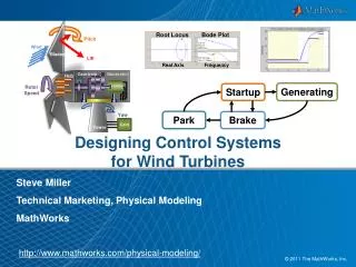
Smart Rotor Control of Wind Turbines Using Trailing Edge Flaps. Matthew A. Lackner and Gijs van Kuik January 6, 2009 Technical University of Delft University of Massachusetts Amherst. Agenda. Background and Objectives Simulation Environment Control Design Fatigue Load Reduction Results

E N D
Smart Rotor Control of Wind Turbines Using Trailing Edge Flaps Matthew A. Lackner and Gijs van Kuik January 6, 2009 Technical University of Delft University of Massachusetts Amherst
Agenda • Background and Objectives • Simulation Environment • Control Design • Fatigue Load Reduction Results • Conclusions
Objective of Smart Rotor Control • Objective: Significant reduction of blade loads by applying spanwise-distributed load control devices. • Faster, local load control is possible. • Active feedback based on local measurements.
Motivation • Turbines are becoming very large, and so are loads. • 5 MW turbine has a 126 m diameter. • Strong motivation to reduce blade fatigue loads for longer lifetime and lower cost.
Sources of Loads Turbulence Wind Shear Tower Shadow • Result is large loads on the blades. • Loads especially pronounced at integer multiples of the rotation frequency: 1P, 2P, etc…
Aerodynamic Load Control Devices adaptive geometry • Shifting of Cl curve or change in α flaps active twist microtabs* *Van Dam 2001
Research Objectives • Evaluate the use of trailing edge flaps for fatigue load reductions. • Compare to baseline controller. • Compare to individual pitch control. • Investigate combined blade pitch and trailing edge flap approach.
Agenda • Background and Objectives • Simulation Environment • Control Design • Fatigue Load Reduction Results • Conclusions
Simulation of NREL 5 MW turbine in Garrad-Hassan ‘Bladed’ program. Simulation and Analysis of Smart Rotor • Bladed: • Aero-elastic design code. • Couple aerodynamics, structural dynamics, and control into a simulation. • Calculate performance and loads.
Can include trailing edge flaps in a variable speed, pitch controller turbine in Bladed. • 70% to 90% span length, 10% chord length. • Aerodynamic data for flaps generated using XFOIL. Modeling a Smart Rotor In Bladed
Simulations Performed in Bladed • 600 second simulations. • Normal and extreme turbulence levels used. • Mean wind speeds of 8, 12, 16, and 20 m/s. • Baseline, individual pitch, flap, and combined blade pitch-flap control used.
Agenda • Background and Objectives • Simulation Environment • Control Design • Fatigue Load Reduction Results • Conclusions
Basic Control Objective • Reduce blade root flapwise bending moment loads: • Utilize flap deflection or pitch angle: • Problem: Rotating reference frame.
Multi-Blade Transformation • Map variables in rotating coordinate system into fixed coordinate system. • Multi-Blade (Coleman) Transformation. • Variables now mapped into “yaw-wise” and “tilt-wise” axes (independent). • Can approximate as time invariant system (LTI).
Feedback Control • Measure blade loads. • Transform to fixed coordinate system. • Two SISO systems for load reduction. • Transform back into rotating coordinates.
Agenda • Background and Objectives • Simulation Environment • Control Design • Fatigue Load Reduction Results • Conclusions
Time Domain Visualization • Segment of the results of the 20 m/s simulation: Flap Control Individual Pitch Control
Quantify using damage equivalent load of the root flapwise bending moment. • Normal turbulence results: Fatigue Load Reduction Results
Load Reductions in the Frequency Domain • Large 1P peak. • Effectiveness depends on frequency of the loads. • Most energy in the low frequency range • Flaps have much higher bandwidth.
Hybrid Controller Results • Also, two hybrid controllers that utilize individual pitch and flap control tested: • HYB1: Reduced individual pitch action, flaps focus on high frequency loads. • HYB2: Identical individual pitch action, flaps focus on high frequency loads. • Fatigue Loads reduced even more than IFC or IPC. • Sizeable load reduction across all frequencies.
Same segment of the 20 m/s simulation. • Significantly different flap behavior. • Potentially reduced pitch usage. Compare to IFC Compare to IPC Hybrid Controller Time Series Results
Limitations of Analysis: Unsteady Aerodynamics? • Bladed assumes quasi-steady aerodynamic behavior. • No lag between changes in angle of attack or flap angle and lift/drag/moment coefficient. • Reduced frequency quantifies degree of unsteadiness: • k = 0: Steady. • 0 < k < 0.05: Quasi-steady. • k > 0.05: Unsteady.
Evaluation of Unsteadiness • Calculate flap deflection spectrum as a function of the reduced frequency. • Integrate spectrum in steady and unsteady region.
Agenda • Background and Objectives • Simulation Environment • Control Design • Fatigue Load Reduction Results • Conclusions
Conclusions • Flaps are effective at reducing fatigue loads. • IPC and IFC differ in how they reduce loads, specifically in which frequency ranges. • A hybrid system offers an interesting combination of IPC and IFC. • Question: What is the optimal balance between load reduction and blade pitch usage in a combined control approach?
Basic Current Control Approaches • Below Rated: Generator torque used to control rotor speed. • Above rated: Generator torque is constant, and blade pitch used to control speed for constant power. Above Rated: Torque and Pitch Control for Constant Power Output Below Rated: Generator Torque Control for Variable Speed Operation
Advanced Current Control Approaches • Individual pitch control (IPC) can also be used for load reduction. • Problem: Increased demand on the pitch system. *van Engelen 2005
Control Implementation • Control code utilizing multi-blade transformation written in Fortran. • PID controllers used. • Compiled as “.dll” file to externally control the Bladed model. • Gain scheduling used for different operating points. • Collective flap angle also used to help with rotor speed control.
Collective Flap Angle • Extra degree of freedom when using flaps. • Collective pitch angle is already used for rotor speed control. • But, can use collective flap angle as well to help with rotor speed control (above rated).
Dynamic Stall Limitations • No dynamic stall model used for flap simulations.
Agenda • Background and Objectives • Simulation Environment • Control Design • Fatigue Load Reduction Results • Effects of Integrating Trailing Edge Flaps • Conclusions
Effects on Pitch System • Different approaches affect the pitch system differently. • Use 16 m/s simulation to investigate.
Summary Pitch System Effects • Pitch Angle: • Pitch Rate:
Agenda • Background and Objectives • Simulation Environment • Control Design • Fatigue Load Reduction Results • Effects of Integrating Trailing Edge Flaps • Extreme Loads • Conclusions
Extreme Loads: Global Step Change • Step increase in wind speed from 15 m/s to 20 m/s. • Uniform across the rotor face. • No wind shear, tower shadow, turbulence, or gravity loads. • Isolate effects of the gusts.
Global Step Change Results • Range used to quantify load reductions: R = Max – Min. • IFC reduces range, IPC does not. • Reduction due to collective flap angle. • Large scale gusts don’t produce tilt/yaw moments.
Extreme Loads: Local Step Change • Wind speed is 15 m/s at almost all points. • At 2, 4, or 6 points, increase it to 20 m/s. • Simulates a local gust on a scale close to the blade length.
Extreme Loads: Local Step Change • Now IFC and IPC are both effective. • Local gusts do generate tilt/yaw moment. • For faster, more local gusts, IFC is much better due to higher bandwidth.
High turbulence levels: Fatigue Load Reduction Results
Dimensionalize Load Reduction Capabilities • At a very basic level, goal of flaps or IPC is to generate a moment on the blade root. • Depends on position, length, and lift change of control surface. • Helps explain effectiveness of IPC, especially at low frequencies.
Effect on Power Production – Region III • Trying to produce constant power output. • Average power is unaffected in all cases. • Use of collective flap angle results in less variability. • IPC results in more variability.
Effect on Power Production – Region II • Reduced power below rated: ~1%. • Due to reduced torque on the flap section.
Explanation for Reduced Power Production – Region II • Average operating angle of attack is not optimal on the flap section. ActualOptimal