Lecture 7
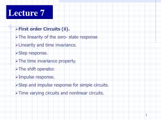
Lecture 7. Frequency Response. Review of CS, CG and CD Amplifier. Voltage Gain of a CS Amplifier. Interpretation: The resistance at the drain Divided by the resistance in the source path. Voltage Gain of a CD Amplifier . Voltage Gain of a CG Amplifier.


Lecture 7
E N D
Presentation Transcript
Lecture 7 Frequency Response
Voltage Gain of a CS Amplifier Interpretation: The resistance at the drain Divided by the resistance in the source path
Voltage Gain of a CG Amplifier If RS=0 and channel length modulation is ignored, Av is
Typical Application of Miller’s Theorem Miller’s theorem is useful when Z appears in parallel with the main signal (i.e. the amplifier)
Limitation of Miller’s Theorem Limitations: Interaction of poles through R3 and C3.
Association of Poles with Nodes Each pole is determined by the product of Total capacitance seen from each node to ground Total resistance seen at the node to ground “Each node in the circuit contributes one pole to the transfer function”
CS Stage • Output Impedance • Input Impedance • “Nodal Method” • Miller Approximation • “Zx” method • Equivalent Circuit Analysis • KCL • Dominant pole
CS Trade-Off For Same IOUT, L↓→W↓→GDS↑(Ro↓) →CDS ↓ Specs: AV=10 Vo,cm=0.6V I(M1)=10 uA gm=AV/RD Gmoverid_1=16.67 Trade-offs in GDS and parasitic capacitance.
CS Trade-Off For Same IOUT, L↓→W↓→GDS↑(Ro↓) →CDS ↓ Specs: Vo,cm=0.6V gm=AV/RD Difficult to achieve high gain and high speed at the same time!
Output Impedance Only Valid if Rs is large!
Input Impedance High frequency approximation Exclude CGS (First order model)
Input Impedance (KCL) High frequency approximation Exclude CGS (In parallel with CGS)
“Nodal Method”(Miller Approximation) It is important to identify the high impedance node! Numerical example: RS=50 Ohms L=2.0 um AV=15 fin=4.65 GHz fout=69.9 MHz 16(10.40fF) 517.8 fF CDB=27.51 fF, RD=60 KOhm
“Nodal Method”(Refined Miller Approximation) (If RS is large!) (Capacitive) (Resistive)
Transmission Zero Transmission Zero Finding a transmission zero in effective Gm.
Source Follower (Strong interaction between XY, making it difficult to associate each pole with each node)
Analysis of Input Impedance Miller Approximation: Av: (Negative Resistance) Can be used to oscillators.
Cascode (Gain from A to X)
DC Input Resistance Will a large Rin increase the miller effect of CS dramatically?
Input Resistance of Common Gate Note that ZL is not infinity if RD is replaced by a current source because ZL is in parallel with CD.
Differential Pair (Differential Mode) (Differential Half Circuit)
Differential Pair (Common-Mode) W3 is made as large as possible to minimize VDSAT.
Differential Pair with High Impedance Load AC Ground (Dominant Pole)
Differential Pair Example GM=166.19 uS GDS=1.3552 uS RD=90 Kohm
Use the Waveform Calculator Add voltages to the calculator Press Evalbefore you plot
Transfer Function 3dB Bandwidth: 317.629 MHz
Small Signal Equivalent Model (Transmission Zero)