Download
1 / 46
460 likes | 534 Vues
Explore the capabilities and advancements of IEEE 802.16 technology, including architecture, channel conditions, security protocols, physical sublayer specifications, QoS support, and mobility management. Learn about spectrum utilization, protocol layering, service convergence sublayers, security features, and PHY introductions with an emphasis on achieving efficient broadband wireless access networks.

E N D
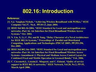
802.16: Introduction Reference: [1] S.J.Vaughan-Nichols, “Achieving Wireless Broadband with WiMax,” IEEE Computer Vol.37, No.6, PP.10-13, June 2004. [2] IEEE Std 802.16-2004, “IEEE Standard for Local and metropolitan area networks--Part 16: Air Interface for Fixed Broadband Wireless Access Systems,” Oct. 2004. [3] N. Liu, X. Li, C. Pei, and B. Yang, “Delay Character of a Novel Architecture for IEEE 802.16 Systems,” Proceedings of Parallel and Distributed Computing, Applications and Technologies (PDCAT 2005), PP.293-296, Dec.2005. [4] IEEE Std 802.16e-2005, “IEEE Standard for Local and metropolitan area networks--Part 16: Air Interface for Fixed Broadband Wireless Access Systems--Amendment 2: Physical and Medium Access Control Layers for Combined Fixed and Mobile Operation in Licensed Bands,” Feb. 2006. [5] C. Cicconetti,L. Lenzini,E. Mingozzi, and C. Eklund, “Qality of service support in IEEE 802.16 networks,” IEEE Network, Vol.20, No.2, PP-55, March-April 2006.
802.16 Architecture(cont.) Point-to-Multipoint Mesh mode
802.16 802.16a/d 802.16e Completed Dec.2001 802.16a: Jan. 2003 802.16d: Oct. 2004 802.16e: Feb. 2006 Spectrum 10 to 66GHz < 11 GHz < 6GHz Channel Conditions Line-of-sight only Non line-of sight Non line-of-sight Bit Rate 32 to 134 Mb/s at 28MHz channelization Up to 75 Mb/s at 20MHz channelization Up to 15 Mb/s at 5 MHz channelization Mobility Fixed Fixed and Portable Mobility, regional Roaming Typical Cell Radius 1 to 3 miles 3 to 5 miles; Maximum range 30 miles 1 to 3 miles IEEE 802.16 extensions
Service Specific Convergence Sublayer • Functions • Provide transformation or mapping of external network data into MAC SDU for MAC CPS • Classify external network data and associate them to proper MAC service flow identifier (SFID) and connection id (CID) • Payload head suppression (optional) • Two convergence sublayer specified • ATM convergence sublayer • Packet convergence sublayer
MAC Common Part Sublayer • Functions • System access • Bandwidth allocation • Connection establishment and maintenance with service flow • Support point-to multipoint (PMP) and mesh modes • Support ARQ scheme • Dynamic uplink (UL) and downlink (DL) • Flexible MAC with various scheduling schemes for real time, non-real time and best effort services
Security Sublayer • Functions • Authentication • Secure key exchange • Encryption • Two component protocols • Encapsulation protocol for dataencryption • Privacy key management protocol (PKM)
Physical Sublayer • WirelessMAN-SC PHY • Single-carrier modulation • Tangeted for 10-66 GHz frequency band • WirelessMAN-SCa PHY • Single-carrier modulation • Frequency bands below 11GHz for NLOS • WirelessMAN-OFDM PHY • OFDM modulation with a FFT size of 256 • Frequency bands below 11GHz for NLOS • AAS and MIMO (also for OFDM-PHY) • WirelessMAN-OFDMA PHY • OFDM modulation with scalable FFT sizes • Frequency bands below 11GHz for NLOS • Hybrid-ARQ • Fast-feedback mechanisms • Handover support
802.16 PHY Introduction(cont.) • Support framing • Support both Time Division Duplex (TDD) and Frequency Division Duplex (FDD) , as well as half-duplex FDD (H-FDD) • Burst transmission format which support adaptive burst profiling • Transmission parameters, including the modulation and coding schemes (burst-profiles) • Downlink Channel Descriptor (DCD) and Uplink Channel Descriptor (UCD) • MAC management messages Downlink Map (DL-MAP) and Uplink Map (UL-MAP)
Internet SS SS BS SS_A SS_B SS_C SS_D Internet Centralized Scheduling Distributed Scheduling BS 802.16 Scheduling PMP (Point-to-Multipoint) IEEE 802.16 Mesh
Internet Centralized Bandwidth request • Congestion at BS • 1 SS active per time slot • Longer route • Serious Delay MAC frame BS Data flow SS A MAC frame SS B MAC frame SS C SS D SS E MAC frame MAC frame SS F SS I MAC frame SS H MAC frame SS G SS K SS J SS J SS J SS J MAC frame SS L SS M SS M Sender Sender Receiver
Internet Distributed Contention for bandwidth • Larger signaling cost BS Data flow SS A SS B SS C SS D SS E MAC frame MAC frame SS F SS I MAC frame SS H MAC frame SS G MAC frame SS K SS J SS J SS J SS J MAC frame SS L SS M SS M Sender Sender Receiver 4
802.16 Mobility ManagementMiddle Domain and Vertical Handoff Reference: [1] J. Y. Hu, and C.-C. Yang, "On the Design of Mobility Management Scheme for 802.16-based Network Environment," Proceedings of IEEE 62nd Semiannual Vehicular Technology Conference (VTC-2005 Fall), PP.25-28 Sept. 2005.
Introduction GR: Gateway Router (Gateway of CIP or GFA of HMIP)
Performance Evaluation-Quantitative Analysis by Simulation(1)
Performance Evaluation (cont.)-Quantitative Analysis by Simulation(2)
802.16e : Mobile Version of 802.16 Cell Radius: 5KM Non-line-of-sight Bandwidth: 15Mbps MH can connect to the BS directly.
Related Work: Traditional Overlay Networks Upper Layer Networks : larger coverage, lower bandwidth Lower Layer Networks: smaller coverage, higher bandwidth Upper Layer Networks Lower Layer Networks
2 3 1 Horizontal & Vertical Handoff 1. Horizontal Handoff 2. Upward Vertical Handoff 3. Downward Vertical Handoff
3 1 2 Coverage-based Handoff Triggering Upper Layer Networks : With larger coverage size and lower bandwidth As soon as received the signal from lower layer, Downward Vertical Handoff C Out of cell coverage, Upward Vertical Handoff B A Lower Layer Networks : With smaller coverage size but higher bandwidth As soon as received stronger signal strength from other cell in the same layer, Horizontal Handoff
Quality of ServiceFramework, Routing, and Scheduling Reference: [1] J. Chen, W. Jiao, and H. Wang, “A service flow management strategy for IEEE 802.16 broadband wireless access systems in TDD mode,” Proceedings of IEEE International Conference on Communications (ICC 2005), Vol. 5, PP. 3422-3426, May 2005. [2] J. Chen, W. Jiao, and H. Wang, “An Integrated QoS Control Architecture for IEEE 802.16 Broadband Wireless Access Systems,” Proceedings of IEEE Global Telecommunications Conference (Globecom 2005), Vol. 5, PP. 3330-3335, Nov.-Dec. 2005. [3] C.C. Yang, Y.T. Mai, and L.C. Tsai, “Cross-Layer QoS Support in the IEEE 802.16 Mesh Network,” Proceedings of 2006 Wireless Personal Multimedia Communications (WPMC 2006), PP.567-571, La Jolla, San Diego, California, Sept. 2006.
Introduction • In IEEE 802.16 standard, scheduling algorithms for uplink and downlink bandwidth allocation in a single frame are undefined. • There is no proposed bandwidth allocation solution considering uplink and downlink simultaneously.
Service Flow Management DSA: Dynamic Service Addition DSC: Dynamic Service Change DSD: Dynamic Service Deletion
DFPQ Hierarchical structure of bandwidth allocation The hierarchical structure of the BW allocation 1st Layer 1. rtPS > nrtPS> BE 2. Downlink > Uplink 2nd Layer 1. rtPS : EDF 2. nrtPS : WFQ 3. BE : RR
Proposed Framework • System Architecture • QoS Parameter Extraction • Centralized Route Selection with QoS Support • Flow Setup • QoS Scheduling
Internet network info Estimated system time node Network Node QoS type T (ms) QoS route request M 192.168.1.0/24 BS A UGS 5 J 192.168.3.0/24 Route response & Flow table construction A rtPS 6 A nrtPS 7 SS A Frame transmission A BE 9 SS B SS C SS D SS E SS F SS I SS G SS H Flow table SS K Rtag Next hop Delay bound QoS flowID SS J SS J SS M SS L 2005 I 10ms rtPS 192.168.1.3/24 192.168.3.4/23 Sender Receiver
Avg. delay and variation by service type with flow data rate 5Mbps
Average Throughput Avg. throughput with flow data rate 5Mbps