Download
1 / 22
240 likes | 607 Vues
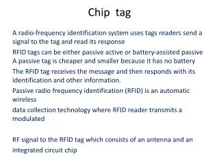
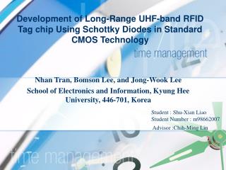
Development of Long-Range UHF-band RFID Tag chip Using Schottky Diodes in Standard CMOS Technology. Nhan Tran, Bomson Lee, and Jong-Wook Lee School of Electronics and Information, Kyung Hee University, 446-701, Korea. Student : Shu-Xian Liao Student Number : m98662007 Advisor : Chih-Ming Lin.

E N D
Development of Long-Range UHF-band RFID Tag chip Using Schottky Diodes in Standard CMOS Technology Nhan Tran, Bomson Lee, and Jong-Wook Lee School of Electronics and Information, Kyung Hee University, 446-701, Korea Student : Shu-Xian Liao Student Number : m98662007Advisor:Chih-Ming Lin
I. INTRODUCTION II. RFID READING RANGE ANALYSISIII. VOLTAGE MULTIPLIER USING SCHOTTKY DIODES IV. ASK DEMODULATORV. OSCILLATOR WITH DIGITAL CALIBRATIONVI. CONCLUSION Outline
I. INTRODUCTION II. RFID READING RANGE ANALYSISIII. VOLTAGE MULTIPLIER USING SCHOTTKY DIODES IV. ASK DEMODULATORV. OSCILLATOR WITH DIGITAL CALIBRATIONVI. CONCLUSION Outline
Introduction • In this paper, we present the characteristics of the Schottky diodes fabricated using Titanium (Ti/Al/Ta/Al)-Silicon (ntype) junction in 0.35 μm CMOS process, and the effect of the size of Schottky diode on the turn-on voltage and the input impedance of the voltage multiplier was investigated. • Based on the measured results of the Schottky diodes, we have designed and tested two key building blocks for UHF-band RFID tag, high efficiency voltage multiplier, and ASK demodulator. • propose architecture for the tag clock generator with digital calibration that allows the transfer of the precise RFID reader timing information to the tag. • Finally, an analysis for long-range RFID tag design considering the limitation caused by the turn-on voltage of tag chip is presented.
I. INTRODUCTIONII. RFID READING RANGE ANALYSISIII. VOLTAGE MULTIPLIER USING SCHOTTKY DIODES IV. ASK DEMODULATORV. OSCILLATOR WITH DIGITAL CALIBRATIONVI. CONCLUSION Outline
RFID Reading Range Analysis Fig. 1. UHF-band RFID tag consisting of antenna and chip.
RFID Reading Range Analysis Fig. 2. (a) The equivalent circuit of the RFID tag antenna and tag chip with parallel RC, (b) The equivalent circuit of the RFID tag antenna and tag chip with series RC.
RFID Reading Range Analysis • we can analyze the factors affecting the detection distance. The first term is the ratio of the antenna open circuit voltage to turn-on voltage of the tag chip, which is determined by Gtag ,RA, EIRP, and, Von,min. The second term indicates that high quality factor is desirable for providing high voltage to the tag chip for increased reading range. The third term is the impedance mismatch factor between the tag antenna and tag chip.
I. INTRODUCTION II. RFID READING RANGE ANALYSISIII. VOLTAGE MULTIPLIER USING SCHOTTKY DIODESIV. ASK DEMODULATORV. OSCILLATOR WITH DIGITAL CALIBRATIONVI. CONCLUSION Outline
Voltage Multiplier Using Schottky Diodes Fig. 3. (a) The equivalent circuit of the RFID tag antenna and the N-stage Dickson voltage multiplier, (b) equivalent circuit model of Schottky diode, (c) equivalent circuit when anode is grounded.
- + Voltage Multiplier Using Schottky Diodes antenna RF Power UHF 900MHz Voltage multiplier antenna antenna Current VDD VDD Current
Voltage Multiplier Using Schottky Diodes antenna RF Power UHF 900MHz Tow-stage Voltage multiplier
Voltage Multiplier Using Schottky Diodes Fig. 4. Measured forward current characteristics of the Schottky diode having (a) different number of parallel connected diodes, (b) different unit finger length with the same overall area, (c) measured junction resistance and junction reactance of the Schottky diodes at 900 MHz as a function of diode size at VD = −0.3 V.
Voltage Multiplier Using Schottky Diodes Fig. 6. Measured output voltage and conversion efficiency of the 6-stage voltage multiplier as a function of tag chip input voltage, Vin.
I. INTRODUCTION II. RFID READING RANGE ANALYSISIII. VOLTAGE MULTIPLIER USING SCHOTTKY DIODES IV. ASK DEMODULATORV. OSCILLATOR WITH DIGITAL CALIBRATIONVI. CONCLUSION Outline
ASK Demodulator Fig. 7. Circuit schematic of the ASK demodulator.
ASK Demodulator Fig. 9. Measured result of the ASK demodulator. The upper is the RF input signal and the lower is the demodulated output.
I. INTRODUCTION II. RFID READING RANGE ANALYSISIII. VOLTAGE MULTIPLIER USING SCHOTTKY DIODES IV. ASK DEMODULATORV. OSCILLATOR WITH DIGITAL CALIBRATIONVI. CONCLUSION Outline
Oscillator With Digital Calibration Fig. 10. The proposed oscillator with digital calibration and waveform description of its operation.
I. INTRODUCTION II. RFID READING RANGE ANALYSISIII. VOLTAGE MULTIPLIER USING SCHOTTKY DIODES IV. ASK DEMODULATORV. OSCILLATOR WITH DIGITAL CALIBRATIONVI. CONCLUSION Outline
Conclusion • An analysis and fabricated Schottky diode in standard 0.35 μm CMOS process were presented for implementing the voltage multiplier for long-range 900 MHz RFID system. • In addition to the detection range analysis, we presented the design of voltage multiplier, ASK demodulator, and architecture for oscillator with digital calibration.