L’Interferometro Virgo
L’Interferometro Virgo. Michele Punturo INFN Perugia a nome della Collaborazione Virgo. Le onde gravitazionali all’IFAE?. Cosa c’è di più di “Alta Energia” della gravitazione?. La collaborazione Virgo. L’esperimento Virgo è realizzato da una collaborazione italo-francese. Firenze/Urbino


L’Interferometro Virgo
E N D
Presentation Transcript
L’Interferometro Virgo Michele Punturo INFN Perugia a nome della Collaborazione Virgo
Le onde gravitazionali all’IFAE? • Cosa c’è di più di “Alta Energia” della gravitazione?
La collaborazione Virgo L’esperimento Virgo è realizzato da una collaborazione italo-francese • Firenze/Urbino • Frascati (LNF) • Napoli • Pisa • Perugia • Roma (Roma1) • Annecy (LAPP) • Lyon (IPNL) • Orsay (LAL) • Nice (ILGA/OCA) • Paris (ESPCI)
Gravitation in the General Relativity Space-time deformation tensor Energy-Momentum tensor • Naïf interpretation of this equation: • Generalized Hooke equation: • General Relativity field equation Strain tensor Stress tensor Elasticity coefficients tensor Space-time is a very rigid medium: Linear approximation of the field equation is allowed A.Einstein proposed the linearized solution of the field equation in 1916 (wave propagating at speed c and with two polarizations):
h+ h 3p/2 p 2p p/2 Phase: 0 Gravitational Waves
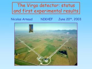
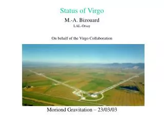
3 km West arm The Virgo Detector Mode cleaner building and tube Control Building 3 km North arm Central Building
Phase(L) -l/100 l/100 0 Working principle l/2 -l/2 0 laser
B8 LB WB Virgo Optical Scheme Q8 1 IMC Laser Q8 2 WE B2 L=3km Q2 1 NB WI PR BS L=5.6m L=3km B7 Q2 2 L=6m L=6.4m B2 NI NE IMC_D1T Q8 2 RFC_DT OB Q8 1 IB RFC OMC Q1 2 B1p EB B1s Q1 1 B1p B5
Local controls The injection system Slave Nd:YVO4 Laser Suspended MC mirror ModeCleanerL = 143 m Diode pump 1W master laser Injection bench Telescope ITF 22 W slave laser ULE monolithic Reference cavity Nd:YAG l=1.064 mm
The Vacuum System • The largest high vacuum system in Europe: • About 7000 m3 • 1.2 m diameter pipe @ 10-7mbar (H2 partial pressure) (6km long) • Reduction of light fluctuation given by air flux • 7 long towers (9m long) with differential vacuum: • Usual 10-7 mbar vacuum in the upper part • 10-9 mbar in the lower part, where mirrors are located • Thermal noise reduction • Mirror contamination control • Short towers @ 10-7mbar
The seismic isolation • What distinguishes Virgo from the competitors is the high sensitivity at low frequency • In a GW detector, the low frequency range is dominated by seismic noise • The typical spectral amplitude of the seismic ground vibration is xg x The Super-Attenuator N stages
Last stage design • The last stage has been designed to minimize the thermal fluctuation of the mirror • The thermal noise is one of the fundamental limits to the Virgo sensitivity in the 5-500Hz frequency range • Equi-partition theorem • Fluctuation-Dissipation theorem
Mirrors • Very demanding requirements in term of absorption, birifrangence of the substrate and the coatings • The Virgo mirrors are the largest (and more expensive) mirrors in the current GW detectors 350 mm 100 mm
The Virgo Commissioning • The last large mirror have been mounted in July 2003 • Virgo is a complex machine that needs a deep tuning of many parameters • Methods and technologies to do that are completely new • Progresses in the commissioning of the machine are demonstrated by the improvement of the duty cycle and by the enhancement of the sensitivity
Commissioning plan Phase A: Commissioning of interferometer arms • Test all aspects of control systems with a simple optical configuration - locking, automatic alignment, second stage of frequency stabilization and suspension hierarchical control (tidal and marionette) • First shake of the sub-systems
Commissioning plan Phase A: Commissioning of interferometer arms • Test all aspects of control systems with a simple optical configuration - locking, automatic alignment, second stage of frequency stabilization and suspension hierarchical control (tidal and marionette) • First shake of the sub-systems
Commissioning plan Phase A: Commissioning of interferometer arms • Test all aspects of control systems with a simple optical configuration - locking, automatic alignment, second stage of frequency stabilization and suspension hierarchical control (tidal and marionette) • First shake of the sub-systems Phase B: Commissioning of interferometer in ‘recombined mode’ • Useful intermediate step towards full interferometer lock • Verify functioning of BS longitudinal control • Re-run all aspects of control system in a more complex configuration • Start noise investigations
Commissioning plan Phase A: Commissioning of interferometer arms • Test all aspects of control systems with a simple optical configuration - locking, automatic alignment, second stage of frequency stabilization and suspension hierarchical control (tidal and marionette) • First shake of the sub-systems Phase B: Commissioning of interferometer in ‘recombined mode’ • Useful intermediate step towards full interferometer lock • Verify functioning of BS longitudinal control • Re-run all aspects of control system in a more complex configuration • Start noise investigations Phase C: Commissioning of Recycled Fabry-Perot interferometer • Run full locking acquisition process • Verify functioning of PR mirror longitudinal control • Re-run SSFS, tidal control and marionette control • Implement complete wave-front sensing control • Continue noise investigations
Commissioning plan Phase A: Commissioning of interferometer arms • Test all aspects of control systems with a simple optical configuration - locking, automatic alignment, second stage of frequency stabilization and suspension hierarchical control (tidal and marionette) • First shake of the sub-systems Phase B: Commissioning of interferometer in ‘recombined mode’ • Useful intermediate step towards full interferometer lock • Verify functioning of BS longitudinal control • Re-run all aspects of control system in a more complex configuration • Start noise investigations Phase C: Commissioning of Recycled Fabry-Perot interferometer • Run full locking acquisition process • Verify functioning of PR mirror longitudinal control • Re-run SSFS, tidal control and marionette control • Implement complete wave-front sensing control • Continue noise investigations Phase D: Noise hunting
Data Analysis • Three kinds of GW sources are expected: • Periodic sources: • Pulsars with quadrupolar moment • Burst: • Non-axisymmetric Supernova explosions • Coalescing binaries • Pair of stars (Neutron stars or Black Holes) rapidly rotating around the center of mass
CB detection • Coalescing binaries detection needs the development of a new analysis strategy • Hypothesis: • The signal shape is well known • The post-Newtonian approximation of the signal • The noise of the ITF is (almost) stationary and gaussian • Optimal filtering method: • Wiener (or matched) filtering • Correlator in time space • “product” in frequency
Detection Strategy • The star masses are unknown parameters • we don’t know the optimal filter, but we can parametrize it • Detection Strategy: • we define a priori the signal-to-noise that we can accept to loose respect to the optimal one (ambiguity function): • we select a frequency range, imposed by the apparatus sensitivity, where to detect the CB signal (25-1000 Hz) • We build-up a “templates” grid (about 45000 templates); the grid step is selected in such a way the SNR lost is below the defined threshold • We perform the matching (correlators) between the ITF output and all the templates • All the matching above threshold, are cross-checked with a sort of c2 test
Template bank is generated hi(t)Hi(w) distributed on all the processes memory Matched Filter implementation x(t)X(w) Double Whitening The integral is evaluated in each process for each template hi(t) Cluster BeoWulf of 23 Opteron 2GHz bi-processor
Conclusions • The Virgo detector commissioning is under way • Firs science run is expected for the end of 2005 – beginning of 2006 • The Data Analysis procedures are under development and testing