Global Cooperation in Linear Collider Design: Insights from the ACFA Workshop
The ACFA Workshop held in Daegu, Korea on July 11, 2005, provided critical insights regarding the international collaboration necessary for the International Linear Collider (ILC). It emphasized the significance of a unified approach in utilizing superconducting technology, as endorsed by ICFA and the International Technology Recommendation Panel. The workshop reaffirmed Asia's pivotal role in hosting the ILC, with strong support for KEK in Japan to lead the Global Design Effort. Participants highlighted the importance of regional collaboration in overcoming scientific and technical challenges associated with the ILC.


Global Cooperation in Linear Collider Design: Insights from the ACFA Workshop
E N D
Presentation Transcript
Report from the GDE Barry Barish ACFA Workshop EXCO, Daegu, Korea 11-July-05
The Energy Frontier ACFA Workshop - Barish
issued on Nov. 3, 2004 at the 9th Plenary ACFA • In August 2004, ICFA has decided on superconducting technology for the future linear collider (LC), by endorsing the resolution of the international technology recommendation panel (ITRP) created by ILCSC under ICFA. The ITRP report emphasizes the importance of world-wide unified approach as a single team to design the international linear collider (ILC). • ACFA has discussed various issues relating to ILC in the plenary meeting of ACFA at VECC, Kolkata in India on 2-3 Nov. 2004, and ACFA came to the following conclusions • ACFA welcomes the truly international nature of the decision on technology for the ILC. This sets the stage for international collaboration in the design efforts for the ILC. • ACFA reaffirms that the ILC, the next major high-energy physics project, should be realized by world-wide efforts. In such International collaboration ACFA and scientists in ACFA countries should play crucial and leading roles. • ACFA reconfirms the importance of hosting ILC in Asia, which will make high energy physics and accelerator science truly global. ACFA Workshop - Barish
ACFA urges the Japanese Government to fully support the efforts of KEK and Japanese scientists to host the ILC in Japan. • ACFA reconfirms that KEK is the best suited institute in Asia for hosting the Central Team of GDI. • ACFA urges KEK to establish the Asian Regional Center for R&D in GDI and encourages other Asian countries to actively participate in GDI. • With ILC entering this important phase, ACFA urges Governments of Asian countries to support participation of their scientists in GDI. • ACFA feels that Asia has wide expertise in accelerator technology which can be directed to develop SCRF technology required for the ILC, and large trained manpower which can make major contributions to the ILC. Because ILC will pose major scientific and technical challenges, there will be several technological fallouts. ACFA therefore feels that by participating in the ILC not only the scientific community of the participating country but also its industry will benefit. ACFA Workshop - Barish
The Community then Self-Organized Nov 13-15, 2004 ACFA Workshop - Barish
The First ILC Meeting at KEK There were 220 participants divided among 6 working groups Working Group 1: Overall Design Working Group 2: Main Linac Working Group 3: Injector, including damping rings Working Group 4: Beam Delivery Systems, including collimator, final focus, etc. Working Group 5: Cavity design: higher gradients, .. Working Group 6: Strategic communication Each working group had three convenors, one from each region ACFA Workshop - Barish
Formal organization begun at LCWS 05 at Stanford in March 2005 when I became director of the GDE The Global Design Effort Technically Driven Schedule
GDE – Near Term Plan • Staff the GDE • Administrative, Communications, Web staff • Regional Directors (one per region) • Engineering/Costing Engineer (one per region) • Civil Engineer (one per region) • Key Experts for the GDE design staff from the world community • Fill in missing skills (later) Total staff size about 20 FTE (2005-2006) ACFA Workshop - Barish
GDE – Near Term Plan • Organize the ILC effort globally • First Step --- Appoint Regional Directors within the GDE who will serve as single points of contact for each region to coordinate the program in that region. (Gerry Dugan (North America), Fumihiko Takasaki (Asia), offered to Brian Foster (Europe)) • Make Website, coordinate meetings, coordinate R&D programs, etc • R&D Program • Coordinate worldwide R & D efforts, in order to demonstrate and improve the performance, reduce the costs, attain the required reliability, etc. (Proposal Driven to GDE) ACFA Workshop - Barish
GDE – Near Term Plan • Schedule • Begin to define Configuration (Aug 05) • Baseline Configuration Document by end of 2005 ----------------------------------------------------------------------- • Put Baseline under Configuration Control (Jan 06) • Develop Reference Design Report by end of 2006 • Three volumes -- 1) Reference Design Report; 2) Shorter glossy version for non-experts and policy makers ; 3) Detector Concept Report ACFA Workshop - Barish
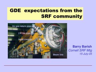
Starting Point for the GDE Superconducting RF Main Linac ACFA Workshop - Barish
Some Key Near-Term Design Choices • Accelerating Gradient • Positron Production mechanism • Design of Damping ring • Site-specific considerations: One or two tunnels? Shallow or deep?, etc • Total cost will be a key determining factor in our ability to get the ILC built. Therefore cost optimization of all systems is of primary importance ACFA Workshop - Barish
Towards the ILC Baseline Design ACFA Workshop - Barish
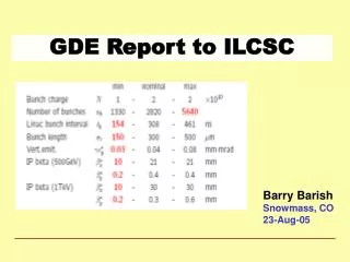
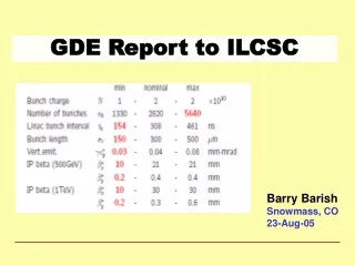
Parameters for the ILC • Ecm adjustable from 200 – 500 GeV • Luminosity ∫Ldt = 500 fb-1 in 4 years • Ability to scan between 200 and 500 GeV • Energy stability and precision below 0.1% • Electron polarization of at least 80% • The machine must be upgradeable to 1 TeV ACFA Workshop - Barish
Specific Machine Realizations • rf bands: • L-band (TESLA) 1.3 GHz l = 3.7 cm • S-band (SLAC linac) 2.856 GHz 1.7 cm • C-band (JLC-C) 5.7 GHz 0.95 cm • X-band (NLC/GLC) 11.4 GHz 0.42 cm • (CLIC) 25-30 GHz 0.2 cm • Accelerating structure size is dictated by wavelength of the rf accelerating wave. Wakefields related to structure size; thus so is the difficulty in controlling emittance growth and final luminosity. • Bunch spacing, train length related to rf frequency • Damping ring design depends on bunch length, hence frequency Frequency dictates many of the design issues for LC ACFA Workshop - Barish
Cost Breakdown by Subsystem Civil SCRF Linac ACFA Workshop - Barish
What Gradient to Choose? ACFA Workshop - Barish
TESLA Cavity ~1m 9-cell 1.3GHz Niobium Cavity Reference design: has not been modified in 10 years ACFA Workshop - Barish
Electro-polishing (Improve surface quality -- pioneering work done at KEK) BCP EP • Several single cell cavities at g > 40 MV/m • 4 nine-cell cavities at ~35 MV/m, one at 40 MV/m • Theoretical Limit 50 MV/m ACFA Workshop - Barish
Gradient Results from KEK-DESY collaboration must reduce spread (need more statistics) single-cell measurements (in nine-cell cavities) ACFA Workshop - Barish
How Costs Scale with Gradient? 35MV/m is close to optimum Japanese are still pushing for 40-45MV/m 30 MV/m would give safety margin Relative Cost Gradient MV/m C. Adolphsen (SLAC) ACFA Workshop - Barish
Evolve the CavitiesMinor Enhancement Low Loss Design Modification to cavity shape reduces peak B field. (A small Hp/Eacc ratio around 35Oe/(MV/m) must be designed). This generally means a smaller bore radius Trade-offs (Electropolishing, weak cell-to-cell coupling, etc) KEK currently producing prototypes ACFA Workshop - Barish
New Cavity Design Re-entrant 28 cell Super-structure More radical concepts potentially offer greater benefits. But require time and major new infrastructure to develop. single-cell achieved45.7 MV/m Q0 ~1010 (Cornell) ACFA Workshop - Barish
Fermilab ILC SCRF Program ACFA Workshop - Barish
Experimental Test Facility - KEK • Prototype Damping Ring for X-band Linear Collider • Development of Beam Instrumentation and Control ACFA Workshop - Barish
Final Focus Test Faclity - SLAC ACFA Workshop - Barish
e- beam diagnostics e- beam diagnostics bunch compressor laser driven electron gun undulator photon beam diagnostics pre-accelerator superconducting accelerator modules TESLA Test Facility Linac - DESY 240 MeV 120 MeV 16 MeV 4 MeV ACFA Workshop - Barish
ILC Siting and Civil Construction • The design is intimately tied to the features of the site • 1 tunnels or 2 tunnels? • Deep or shallow? • Laser straight linac or follow earth’s curvature in segments? • GDE ILC Design will be done to samples sites in the three regions • North American sample site will be near Fermilab • Japan and Europe are to determine sample sites by the end of 2005 ACFA Workshop - Barish
Fermilab ILC Civil Program A Fermilab Civil Group is collaborating with SLAC Engineers and soon with Japanese and European engineers to develop methods of analyzing the siting issues and comparing sites. The current effort is not intended to select a potential site, but rather to understand from the beginning how the features of sites will effect the design, performance and cost ACFA Workshop - Barish
Parameters of Positron Sources ACFA Workshop - Barish
Positron source Conventional source Undulator-based source B=0.75 T 5 mm gap ACFA Workshop - Barish
Laser Compton Source ACFA Workshop - Barish
Beam Delivery Systems -- Challenges • Transport the high-energy beam from the end of the main linac to the interaction point • Transport the post-collision spent beam and beamstralung to the dumps • Provide collimation for control of backgrounds • Provide machine protection systems for errant beams • Provide collision point maintenance through the use of fast feedback systems (inter-train and intra-train) ACFA Workshop - Barish
ILC Strawman Layout tuneup dump lines 20 mrad ILC FF9 (x 4) Mark Woodley ACFA Workshop - Barish
Accelerator Physics Challenges • Develop High Gradient Superconducting RF systems • Requires efficient RF systems, capable of accelerating high power beams (~MW) with small beam spots(~nm). • Achieving nm scale beam spots • Requires generating high intensity beams of electrons and positrons • Damping the beams to ultra-low emittance in damping rings • Transporting the beams to the collision point without significant emittance growth or uncontrolled beam jitter • Cleanly dumping the used beams. • Reaching Luminosity Requirements • Designs satisfy the luminosity goals in simulations • A number of challenging problems in accelerator physics and technology must be solved, however. ACFA Workshop - Barish
Test Facility at KEK ACFA Workshop - Barish
Test Facility at SLAC ACFA Workshop - Barish
e- beam diagnostics e- beam diagnostics bunch compressor laser driven electron gun undulator photon beam diagnostics pre-accelerator superconducting accelerator modules TESLA Test Facility Linac - DESY 240 MeV 120 MeV 16 MeV 4 MeV ACFA Workshop - Barish
Fermilab ILC SCRF Program ACFA Workshop - Barish
ACFA Joint Linear Collider Physics and Detector Working Group • “Our task is to continue studies on physics at the linear collider more precisely and more profoundly, taking into account progresses in our field, as well as on developments of detector technologies best suited for the linear collider experiment. As we know from past experiences, this will be enormously important to realize the linear collider.” • Akiya Miyamoto ACFA Workshop - Barish
Higgs Coupling and Extra Dimensions • ILC precisely measures Higgs interaction strength with standard model particles. • Straight blue line gives the standard model predictions. • Range of predictions in models with extra dimensions -- yellow band, (at most 30% below the Standard Model • The models predict that the effect on each particle would be exactly the same size. • The red error bars indicate the level of precision attainable at the ILC for each particle • Sufficient to discover extra dimensional physics. ACFA Workshop - Barish
Beam Detector Interface Tauchi LCWS05 ACFA Workshop - Barish
The GDE Plan • The Machine • Accelerator baseline configuration will be determined and documented (BCD) by the end of 2005 • R&D program and priorities determined (proposal driven) • Baseline configuration will be the basis of a reference design done in 2006 • The Detector(s) • Determine features, scope: one vs two, etc (same time scale) • Measure performance of the baseline design • Beam delivery system and machine detector interfaces • Define and motivate the future detector R&D program ACFA Workshop - Barish