IX. X-ray diffraction
IX. X-ray diffraction. 9-1. Production of X-ray. Vacuum, thermionic emission, high voltage, and a target. http://www.arpansa.gov.au/radiationprotection/basics/xrays.cfm. Energetic electron hitting a target. Braking radiation. Characteristic X-ray. Auger electrons.

IX. X-ray diffraction
E N D
Presentation Transcript
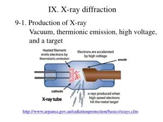
IX. X-ray diffraction 9-1. Production of X-ray Vacuum, thermionic emission, high voltage, and a target http://www.arpansa.gov.au/radiationprotection/basics/xrays.cfm
Energetic electron hitting a target Braking radiation Characteristic X-ray Auger electrons
(i) Braking radiation: Target v2 v0 v1 V2 > V1 I V2 V1 Short wavelength limits
(ii) characteristic radiation Nonradiative transition M } { Auger electron 3S Characteristics X-Ray photon L3 L3 L3 2P L2 L2 L2 2S L1 L1 L1 Excitation source K K2 K1 Radiative transition K K k 1S The figure in Note is wrong!
(iii) Cu K radiation Cu K1 =1.54050 Å Cu K2=1.54434 Å Cu K=1.5418 Å High angle line Low angle line Why we can resolve K1 and K2double lines at high angle?
9-2. X-ray diffraction (i) Laue method: variable, white radiation, fixed (ii) Diffractometer method: fixed, characteristic radiation, variable (iii) Powder method: fixed, characteristic radiation, variable (iv) Rotating crystal method: fixed, characteristic radiation, variable
(1) Laue condition Von Laue derived the “ Laue conditions “ in 1912 to express the necessary conditions for diffraction. Assume that are three crystal lattice vectors in a crystal Similarly,
Very often , the Laue conditions are expressed as Unit vector The three Laue conditions must be satisfied simultaneously for diffraction to occur. The physical meaning of the 3 Laue conditions are illustrated below.
1st Laue conditions The path difference between the waves equals to The criterion for diffraction to occur is or integer
For 1-dimensional crystal Cones of diffracted beams for different h
Stereographic projection representation for 1-D crystals The projection of diffracted beams for h = 0 is a great circle if the incident beam direction is perpendicular, i.e. The projection of diffracted beams for h = 0 is a small circle if the incident beam direction is not perpendicular
2nd Laue condition integer
For a two-dimensional crystal The 1st and 2nd conditions are simultaneously satisfied only along lines of intersection of cones.
Stereographic projection for 2-D crystals The lines of intersection of cones are labeled as (h , k)
3rd Laue condition l: integer For a single crystal and a monochromatic wavelength, it is usually no diffraction to occur
(2) Laue photograph Laue photograph is performed at “ single crystal and variable wavelength ”. (2-1) Ewald sphere construction or white radiation : wavelength is continuoue; lwl and swl: the longest and shortest wavelength in the white radiation.
Two Ewald spheres of radius OA and OB form in between two spherical surface meets the diffraction condition since the wavelength is continuous in white radiation.
http://www.xtal.iqfr.csic.es/Cristalografia/archivos_06/laue1.jpghttp://www.xtal.iqfr.csic.es/Cristalografia/archivos_06/laue1.jpg
(2-2) zone axis The planes belong to a zone We define several planes belong to a zone [uvw], their plane normal [hi kili] are perpendicular to the zone axis, In other words,
In the Laue experiments, all the planes meet the diffraction criterion. Each plane meets the 3 Laue conditions. for all the plane belonged to the zone [uvw].
If we define The path difference between the waves equals to
(A) for the condition < 45o For all the planes (hikili) in the same zone [uvw]
Therefore, all the diffracted beam directions Ŝ1', Ŝ2', Ŝ3', …Ŝi' are on the same cone surface. (B) for the condition > 45o The same as well
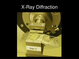
Instrumentation at MSE, NTHU Shimatsu XRD 6000
If a new material is deposited on Si(100) and put on the substrate holder in the diffractometer set-up, is always parallel to the Si(100) surface normal. Any sample 2 1
Ewald sphere construction 21 1 o Si (100) substrate Rotate the incident beam at until meets the diffraction condition at
This is equivalent to at least one crystal with (h1k1l1) plane normal in parallel with the Si(100) surface normal. When the incident beam is rotated (rotating the Ewald sphere or rotating the reciprocal lattice), will meet the diffraction condition at 22 1 2 o Si (100) substrate
This is equivalent to at least one crystal with (h2k2l2) plane normal in parallel with the Si(100) surface normal. If only one plane of the film is observed in the diffractometer measurement, the film is epitaxial or textured on Si(100).
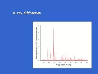
(b) XRD spectrum of AlN deposited on Si(100) A large number of grains with AlN(002) surface normal in parallel to Si(100) surface normal, but small amount of grains of AlN(100) and AlN(101) are also in parallel to Si(100) surface normal.
9-2-2-2 X-ray rocking curve X-ray rocking is usually used to characterize the crystal quality of an epitaxial or textured film. At a certain diffraction condition the incident and outgoing directions of X-ray are fixed and the sample is rotated by scan. Careful scan around a specific diffraction peak!
When the crystal is rotated by d, this is equivalent to the detector being moved by the same d. (?) The FWHM of the diffracted peak truly reflects the width of each reciprocal lattice point, i.e. the shape effect of a crystal. (by high resolution!)
2 o 2(+) o
9-2-2-3. Scan The scan is used to characterize the quality of the epitaxial film around its plane normal by rotating (0-2)
Example: the crystal quality of highly oriented grains each of which is a columnar structure shown below Each lattice point in the reciprocal lattice will be expanded into an orthorhombic volume according to the shape effect. The scan can be used to confirm the orientation of the columnar structure relative to the substrate.
Shape effect ( ) Reciprocal lattice points grain 2 2
2 0 360
9-2-4 Powder method (Debye-Scherrer Camera) http://www.adias-uae.com/plaster.html
http://www.stanford.edu/group/glam/xlab/MatSci162_172/LectureNotes/06_Geometry,%20Detectors.pdfhttp://www.stanford.edu/group/glam/xlab/MatSci162_172/LectureNotes/06_Geometry,%20Detectors.pdf
(a) Ewald sphere construction Reciprocal lattice ofa polycrystalline sample B.D. Cullity Powder can be treated as a very larger number of polycrystals with grain orientation in a random distribution Reciprocal lattice become a series of concentric spherical shells with as their radius
Intersection of Ewald sphere with spherical reciprocal lattice! forms a cone resulting from the intersection between Ewald sphere and the spherical reciprocal lattice. The intersection between the concentric spherical shells of in radius and the Ewald sphere of radius are a series of circles (recorded as lines in films)
Example Debye-Scherrerpowder pattern of Cu made with Cu Kradiation