Extrusion
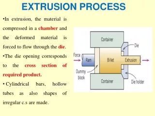
Extrusion. 3D Shapes. Basic methods of creating 3D shapes using a 2D sketch: Extruding “Stretching” the shape from its original 2D outline to a 3 rd Dimension Revolving Creating a 3D object by drawing a 2D cross-section and revolving that around an axis. Extrusion.


Extrusion
E N D
Presentation Transcript
Extrusion Extrude
3D Shapes Basic methods of creating 3D shapes using a 2D sketch: Extruding “Stretching” the shape from its original 2D outline to a 3rd Dimension Revolving Creating a 3D object by drawing a 2D cross-section and revolving that around an axis Extrude
Extrusion Closed Profile on a 2D Plane Direction Amount First Extrusion New 2D Planes Created Add or Subtract Finished Product Extrude
Adding Material Positive Extrusion 2D Profile used to add material at a specified length 2D Profile extruded to next surface or to selected surfaces Extrude
Subtracting MaterialNegative Extrusions 2D Profile used to subtract material at a specified length 2D Profile used to cut to selected surfaces or through all Extrude
SolidWorks: Extrude Dialogue Box A Blind Extrusion is an Extrusion to a selected depth Reverse Direction Extrusion Options Depth Extruded Cut is for Negative Extrusions and contains many of the same options Direction 2 (if needed) Extrude
SolidWorks: Base Extrusion This profile is a nested profile and thus the final result only adds material between the outer and inner lines A base feature can be created by extruding a 2D sketch located on one of the original planes Extrude
SolidWorks: Sketching on Surfaces Once the first extrusion is completed new faces are available for sketching. Click the sketch button then select the 2D surface or plane that is necessary for the next step Extrude
SolidWorks: Extruded Cut Once the base feature is created, a 2D sketch can be drawn on one of the faces of the new object The depth can be determined by a numerical distance or other options for Extruded Cuts including: Through All and to Next Surface Extrude
SolidWorks: Feature Extrusions Extrusions can continue to be added and the resulting protrusion will be joined to the original base If a profile overlaps the original geometry then the two extrusions will merge to create one part Extrude
SolidWorks: Editing Features To edit any feature right click on the feature in the model tree • The dialogue window allows you to (from left to right, top to bottom): • Edit Feature • Edit Sketch • Suppress Feature • Roll Back • Hide • Zoom to Feature • Normal View to Feature • Change appearance (color) Extrude
Extrusion Wrap Up Extrusions • Positive Extrusion • stretch a 2D profile to 3D • Negative Extrusion • remove material from a 3D model (cut) • Geometries merge • Loops have to be CLOSED Homework Assignment Create shape shown using positive and negative extrusions. Shape is important, dimensions are not. Print off Isometric with Name, Seat Number, and Instructor. Shape in text Problem 6.4 (f) Extrude
In-Class Assignment Draw this camera with positive and negative extrusions. Add your name and turn in for the in-class problem. Extrude