Download
1 / 13
140 likes | 408 Vues
IEEE EMBC 2006 , 30 August – 3 September, 2006, New York City. Intracardiac Electrical Bioimpedance as a Basis for Controlling of Pacing Rate Limits Andres Kink , Rodney W. Salo , Mart Min , Toomas Parve , and Indrek Rätsep

E N D
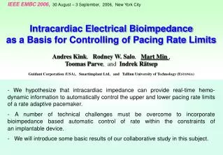
IEEE EMBC2006, 30 August – 3 September, 2006, New York City Intracardiac Electrical Bioimpedanceas a Basis for Controlling of Pacing Rate Limits Andres Kink, Rodney W. Salo,Mart Min , Toomas Parve, and Indrek Rätsep Guidant Corporation (USA), Smartimplant Ltd, and Tallinn University of Technology (ESTONIA) -We hypothesize that intracardiac impedance can provide real-time hemo- dynamic information to automatically control the upper and lower pacing rate limits of a rate adaptive pacemaker. -A number of technical challenges must be overcome toincorporate bioimpedance based automatic control of rate within theconstraints of animplantable device. - We will introduce some basic results of our collaborative study in this subject.
IEEE EMBC 200630 Aug – 3 Sept 2006, New York City2 A.Kink, R.W.Salo, M.Min, T.Parve, I.Rätsep. Intracardiac Electrical Bioimpedance as a Basis for Controlling of Pacing Rate Limits 1. Over pacing and Under pacing The pacing rate PR should follow the body workload Wbody, which correlates with minute ventilation MV=RRxTV estimated, e.g., through a transthoracic bioimpedance (Fig. 1). Problem: Inadequate estimation can lead to dangerous, too high or too low PR Automatic control of upper and lower PR limits prevents both, over and under pacing. Over pacing takes place when - the cardiac cycle is too short to permit adequate filling, thus limiting cardiac output, or - cardiac output is maintained, but at the cost of excessive oxygen consumption. Under pacing occurs when the sensed demand is low and the paced rate is either - insufficient to meet first cardiac or overall metabolic demand, or -the cardiac output is maintained only by an excessive increases in preload and high filling pressures. Fig. 1.A rate-adaptive pacing system
IEEE EMBC 200630 Aug – 3 Sept 2006, New York City3 A.Kink, R.W.Salo, M.Min, T.Parve, I.Rätsep. Intracardiac Electrical Bioimpedance as a Basis for Controlling of Pacing Rate Limits 2. Why the paced heart rate is critical? Metabolic demand can exceed the capabilities of a damaged heart (W > E). Problem: artificial pacing may drive the heart into failure. A “positive” balance E ≥ W must be maintained ! Pacing rate limits are needed, but incorrect, fixed limits can exacerbate problems such as: - Postural hypotension, caused by shifts in blood volume to lower extremities, which can lead tosyncope, and - Neurogenic syncope, which is even more insidious problem because asudden drop in blood pressure may occur minutes after the precipitating event. Dynamically adaptive limits are needed! Sdem < Ssup Wext ≈ ΔP · SV E ≈ ΔP · tdiast external work energy supply Fig. 2. Ventricular pressure-volume loop (a), and variation of arterial pressure (b): 1. HR = Hrest 2. HR = 2·Hrest
IEEE EMBC 200630 Aug – 3 Sept 2006, New York City4 A.Kink, R.W.Salo, M.Min, T.Parve, I.Rätsep. Intracardiac Electrical Bioimpedance as a Basis for Controlling of Pacing Rate Limits 3. Myocardial Energy? The area Sdem ≈ ΔP · SV in Fig. 3 represents the myocardium’s external workWext. The area Spot ≈ ΔP·(Ves‑ V0 ) ∕ 2 is proportional to the myocardium’s internal workWint , Total energy consumptionWof myocardium can be expressed as Scons = Sdem+ Spot= = ΔP·(2·SV + Ves‑ V0) ∕ 2 Fig. 3. P-V diagram with energy consumption areas Sdemand Spot, where ESPVR is the end-systolic P-V relationship line.
IEEE EMBC 200630 Aug – 3 Sept 2006, New York City5 A.Kink, R.W.Salo, M.Min, T.Parve, I.Rätsep. Intracardiac Electrical Bioimpedance as a Basis for Controlling of Pacing Rate Limits 4. Myocardial Energy and Impedance The myocardial energy balance can be expressed as Ssup = Sdem∙ kpot , wherekpotexpresses the role of internal work and depends almost linearly on relative stroke volumeSV/Ves ,but only very slightly on relative pressuresPas/Pad(Fig.4). It can be approximated as kpot= (1.7-1.8) SV/Ves Rough estimation of the overall energy balance E = Wext + Wint does not require pressure measurements. We can extract the needed information (time intervals and relative ventricular volumes) solely from the measured intracardiac impedance waveform ! Fig. 4 Relationship of the relative energy demandSdem/Spotversus relative stroke volumeSV/Vesfor some values ofPas /Pad.
IEEE EMBC 200630 Aug – 3 Sept 2006, New York City6 A.Kink, R.W.Salo, M.Min, T.Parve, I.Rätsep. Intracardiac Electrical Bioimpedance as a Basis for Controlling of Pacing Rate Limits 5. Experiments and Modeling • the actual stroke volume in mlmeasured by aortic flowmeter in an intact canine model, • and • 2) the peak-to-peak resistance change, ΔR(in ohms), during a cardiac cycle measured with a four electrode right ventricular catheter. In Fig.5. is shown an experimental comparison between Fig. 5. A comparison between right ventricular stroke volume measured by aortic flow, and right ventricular peak-to-peak resistance, ΔR, in a dog during an infusion of dobutamine.
IEEE EMBC 200630 Aug – 3 Sept 2006, New York City7 A.Kink, R.W.Salo, M.Min, T.Parve, I.Rätsep. Intracardiac Electrical Bioimpedance as a Basis for Controlling of Pacing Rate Limits Fig.6 shows the relationship between actual volumes, and the volumes that were calculated from impedances (vertical axis). A finite-difference model of heart conductance containing a standard implantable electrode system was used to generate these data. The near-to-linear relationship indicates the feasibility of following changes in relative stroke volume using a standard electrode system. Fig. 6. A comparison between the stroke volumes computed from resistances (vertical axis) measured across the left ventricle (from right ventricular apex to left ventricular free wall) and the actual left ventricular volumes (horizontal axis).
IEEE EMBC 200630 Aug – 3 Sept 2006, New York City8 A.Kink, R.W.Salo, M.Min, T.Parve, I.Rätsep. Intracardiac Electrical Bioimpedance as a Basis for Controlling of Pacing Rate Limits Stabilizing the Stroke Volume The energy supply diminishes with the higher rate because the dia-stolic time tdiast shortens (Fig.7). When stabilizing the stroke volume at the predetermined reference valueSV = SVref ,(see Fig.8) the myocardium’s energy consumption will remain constant. The energy balance can be expressed directly through the pacing rate. Fig. 7. Dependence of the stroke volume SV and diastolic time tdiast on pacing rate PR. Substituting tdiast =(60/PR)–tsyst in kpot·(SVref) · ΔP≤ (tdiast)·ΔP we obtain thatPR≤ 60 SVref ⁄ (1 + kpot· SVref· tsyst).
IEEE EMBC 200630 Aug – 3 Sept 2006, New York City9 A.Kink, R.W.Salo, M.Min, T.Parve, I.Rätsep. Intracardiac Electrical Bioimpedance as a Basis for Controlling of Pacing Rate Limits A closed loop stabilizer of Stroke Volume Pacing rate is controlled automatically as a tool to stabilize the stroke volume SVactual = SVref using a closed-loop or feedback system. Fig. 8. A closed-loop system to control pacing rate by maintaining a fixed stroke volume.
IEEE EMBC 200630 Aug – 3 Sept 2006, New York City10 A.Kink, R.W.Salo, M.Min, T.Parve, I.Rätsep. Intracardiac Electrical Bioimpedance as a Basis for Controlling of Pacing Rate Limits Modeling of the Heart and Intracardiac Impedance Fig. 9.3D digital model of the heart with 16 measurement electrodes. Fig. 10.Experimentation on a virtual heart reflecting impedance variations during a cardiac cycle measured between different pairs of electrodes: a) 1 and 4, b) 2 and 4, c) 3 and 4, applying excitation current to electrodes 1 and 4.
IEEE EMBC 200630 Aug – 3 Sept 2006, New York City11 A.Kink, R.W.Salo, M.Min, T.Parve, I.Rätsep. Intracardiac Electrical Bioimpedance as a Basis for Controlling of Pacing Rate Limits Experimentation with an isolated pig’s heart A picture of an experimental setup with an isolated pig heart is shown in Fig. 11. The resuscitated heart was continuously perfused by an artificial blood circulation system permitting active experimentation for several hours. An original impedance measurement and data acquisition system was developed for performing in vivo experiments. PCT Patent Application WO2005/122889 A1(29.12.2005). Fig. 11.Experimental setup with an isolated pig’s heart.
IEEE EMBC 200630 Aug – 3 Sept 2006, New York City12 A.Kink, R.W.Salo, M.Min, T.Parve, I.Rätsep. Intracardiac Electrical Bioimpedance as a Basis for Controlling of Pacing Rate Limits 6. Discussion As a result of our study, we assume that: A. it becomes possible to use 1) hemodynamic information derived from bioimpedance measurements alone for feed-forward control of pacing rate, while 2) simultaneously monitoring myocardial energy balance to preclude potentially damaging rates using feedback corrections. B. the pacing rate is only an intermediate parameter, available as a control tool to 1) satisfy the patient’s metabolic demands, and 2) fulfilling the myocardium’s energy supply needs. C. a potential benefit of stabilizing the stroke volume we would maintain a relatively constant preload and myocyte “stretch”, minimizing hypertrophic signaling and subsequent cardiac remodeling.
IEEE EMBC 200630 Aug – 3 Sept 2006, New York City13 A.Kink, R.W.Salo, M.Min, T.Parve, I.Rätsep. Intracardiac Electrical Bioimpedance as a Basis for Controlling of Pacing Rate Limits Conclusions Our experimental studies and theoretical speculations confirm that: - Increased concern over cardiac efficiency and maintenance of energy balance within the heart may be addressed by novel pacing control algorithms that require only relative stroke volume information, derivable from bioimpedance measurements applied to a feedback control system. - New impedance measurement methods can permit more reliable results to make such feedback systems feasible for rate control. - Model based design appears to be a fruitful tool for the synthesis of complicated and nonlinear closed loop systems for pacing rate control. Thank you for your attention !