Download
1 / 23
230 likes | 452 Vues
Electrical Safety at the Holifield Radioactive Ion Beam Facility. B. Alan Tatum SNS Electrical Safety Workshop June 2-3, 2004. Outline. Overview of the HRIBF Specific Electrical Hazards at HRIBF Hazard mitigation Organizational structure Inspection Processes Training Challenges.

E N D
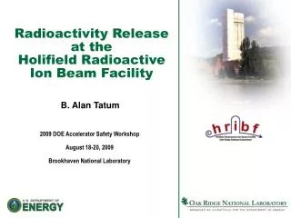
Electrical Safety at the Holifield Radioactive Ion Beam Facility B. Alan Tatum SNS Electrical Safety Workshop June 2-3, 2004
Outline • Overview of the HRIBF • Specific Electrical Hazards at HRIBF • Hazard mitigation • Organizational structure • Inspection Processes • Training • Challenges
Mission • HRIBF is an accelerator-based National User Facility funded by DOE-NP to conduct nuclear structure and astrophysics research using short-lived, radioactive beam species produced primarily by the isotope separator on-line (ISOL) technique.
Overview of Major Systems and Key Issues in ISOL Technology at HRIBF • Driver Accelerator • ORIC, a k=105 isochronous cyclotron • RIB Production (Injector) Platform • Presently a single, rather small injector • Target/Ion Sources • Kinetic Ejection Negative Ion Source (KENIS) for production of proton-rich beams such as 17F and 18F from Hafnium oxide (HfO2) target • Electron Beam Plasma (EBP) source for neutron-rich RIBs, pure Sn, etc…from Uranium Carbide (UC2) targets • Multi-sample sputter source for 7Be beams • Batch mode source for 56Ni • Post Accelerator • 25 MV tandem electrostatic accelerator w/ negative ion injection • Experimental Systems • Recoil Mass Spectrometer (nuclear structure) • Daresbury Recoil Separator (astrophysics) • Enge Spectrometer • General purpose end stations • Target and Ion Source Development and Testing Facilities • Low power On-line • Two off-line • High Power Target Laboratory (under construction)
Primary Hazards at HRIBF • Radiological • SF6 insulating gas • Compressed gases • High electric fields • High magnetic fields • RF • Confined spaces • Rotating Equipment • Chemical • Electrical
Ion Source Assembly Electrostatic Deflector RF Power Amplifier Tube RF Structure Coaxial Magnetic Channel Lower Magnetic Channel Beam Line to RIB Injector Magnet Structure Driver Accelerator: Oak Ridge Isochronous Cyclotron (ORIC)
ORIC Electrical Systems • High current power supplies to 90V and 6000 Adc • Motor-Generator sets (5000 hp synchronous motor with dual 1750 kVA generators 360V, 5000 A dc) • RF power amplifier system (20kV, 30A anode) • High voltage (5kV, 3A ion source, 80kV, 7.5mA deflector)
RIB Production (Injector) System Two interconnected platforms are biased at -300kV dc Target/ion source biased at 60kV dc relative to platform Procedure & training Redundant hardwired interlocks Mechanical shorting rod LOTO
RIB Injector Electrical Hazards • Electrostatic quadrupoles and electrostatic steerers, 5kV w/SHV connectors • Multiple high voltage ion source power supplies 5-300 kV dc • Ionization gauges • Dipole magnet, 385 Adc • Power supplies in tight spaces • Remotely coupled robotic handling system for activated target ion sources • Faraday cups, BPMs • Cesium charge exchange cell with ac heaters • EPICS/PLC-based control systems
Post Accelerator: 25 MV Tandem Electrostatic Accelerator • Largest in the World • NEC Pelletron charging chain design • Nominal max 25 MV terminal voltage (Has operated at higher voltages) • “Folded” Design • Considerably more internal ion optics than any other electrostatic accelerator • Beam energy is EI + VT (Q+1), for single stripping (EI=inject E, Q=charge state) • Maintenance access by a “central service platform” or by an “annular service platform” • Contained in an 80,000 ft3 Pressure vessel • Insulated with approx. 200,000 lbs SF6 gas ,
25 MV Tandem • Electrical hazards are enclosed in the pressure vessel including generators • Controls and power supplies vulnerable to high voltage discharges • LO/TO required prior to pressure vessel entry Low Energy Acceleration Tube High Energy Acceleration Tube
Stable Ion Injector • Manufactured by NEC • Operates to -300kv • Houses multiple ion sources which produce stable ion beams for experiments and experimental setup • Low energy beam optics • Electrical safety devices • Enclosed in an interlocked cage • Rotating beacons • Grounding hooks
Mitigating Hazards: Organization • Electrical Safety Officer (1), member of the ORNL ESC • Electrical Engineers (4 +1 at ORELA) • Control system engineer (1) • Accelerator Operators (6) • Electricians (3) • Instrument Technicians (2) • Qualified Electrical Workers (numerous)
Mitigating Hazards: Inspection Processes • “Daily” assessments by electrical engineers who are involved in both operations and development • Quarterly self assessment program • Device mentors: in-house research staff responsible for experimental end-stations • End-station reviews • Experiment reviews • Work planning & JHE with crafts • Culture shift that blends expertise from facility operations and experimental systems • Culture in which the staff wants to “do the right thing” • Staff has taken ownership of safety
Training • Physics Division Electrical Safety • Electrical shock, burns, current effects • Common electrical devices • Flexible cords, extension cords, GFCIs, batteries • Electrical hazards specific to the facility • Accelerators, spectrometers, rf, power supplies, magnets, coils • High voltage safety • Safe work practices • PPE, wet areas, circuit breakers, insulated tools, conductive materials, fires, signs, barriers • Equipment • Grounding & bonding, flammable gases, clearances, interlocks • RIB Injector Electrical Safety • Platform and ion source voltages, LO/TO, special access situations • Qualified Electrical Worker • Exam and authorization required • Safety Flash Distribution
Challenges • Maintaining and updating aging equipment • Segregating systems for easier maintenance • How many levels of redundancy? • What do you trust to software/PLC systems? • Determination of qualified electrical workers • Appropriate PPE for Electricians and Instrument Technicians • Balancing safety with R&D. Pressures of delivering beam requires rapid recovery from failures. • Training visitors (experimentalists) in electrical safety