Download

1 / 25
280 likes | 327 Vues
This investigation delves into Submerged Friction Stir Welding (SFSW), exploring its benefits and applications in underwater repair and construction. The study compares submerged and conventional dry FSW, providing insights on grain size reduction, tensile strength, and overall welding quality.

E N D
An Investigation into Submerged Friction Stir Welding Vanderbilt University Welding Automation Laboratory: Nashville, TN Thomas S. Bloodworth III Paul A. Fleming David H. Lammlein Tracie J. Prater Dr. George E. Cook Dr. Alvin M. Strauss Dr. Mitch Wilkes Los Alamos National Laboratory: Los Alamos, NM. Dr. Thomas Lienert Dr. Matthew Bement
Overview • Introduction • Objective • VUWAL Test Bed • Experimental Setup • Materials Testing • Results and Conclusions • Future Work • Acknowledgements
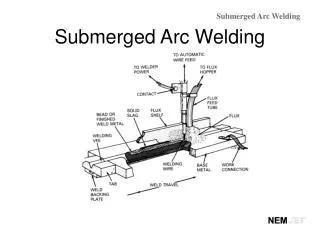
Introduction • Friction Stir Welding (FSW) • Frictional heat with sufficient stirring plasticizes weld-piece (Thomas et al) • Advantageous to conventional welding techniques • No Fumes • Solid State • Non-consumable Tool • Welds maintain up to 95% of UTS compared to parent material
Introduction • Light weight materials used in production (e.g. Aluminum) • FSW is used primarily to weld Aluminum Alloys (AA) • Process currently becoming more prevalent: • Aerospace (e.g. Boeing, Airbus) • Automotive (e.g. Audi) • Marine (SFSW / IFSW)
Objective • Submerged / Immersed FSW (SFSW / IFSW) • Processing of the weld piece completely submerged in a fluid (i.e. water) • Greater heat dissipation reduces grain size in the weld nugget (Hofmann and Vecchio) • Increases material hardness • Theoretically increases tensile strength
Objective • Hofmann and Vecchio show decrease in grain size by an order of magnitude • Increase in weld quality in SFSW may lead to prevalent use in underwater repair and/or construction (Arbegast et al) • Friction Stir Spot Welds (FSSW) • Repair of faulty MIG welds (TWI) • Process must be quantitatively verified and understood before reliable uses may be attained
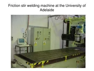
VUWAL Capabilities • VUWAL Test Bed: Milwaukee #2K Universal Milling Machine utilizing a Kearney and Treker Heavy Duty Vertical Head Attachment modified to accommodate high spindle speeds. • 4 – axis position controlled automation • Experimental force and torque data recorded using a Kistler 4 – axis dynamometer (RCD) Type 9124 B • Rotational Speeds: 0 – 5000 rpm • Travel Speeds: 0 – 100 ipm
VUWAL Test Bed • Anvil modified for a submerged welding environment • Water initially at room temperature • Equivalent welds run in air and water for mechanical comparison (i.e. Tensile testing)
Experimental Setup • Optimal dry welds run 2000 rpm, 16 ipm • Wet welds speeds: 2000 – 3000 rpm, travel speeds 10 – 20 ipm • Weld samples • AA 6061-T6: 3 x 8 x ¼” (butt weld configuration) • Tool • 01PH Steel (Rockwell C38) • 5/8” non – profiled shoulder • ¼” – 20 tpi LH tool pin (probe) of length .235” • Clockwise rotation • Single pass welding
Experimental Procedure • Shoulder plunge and lead angle: .004” , 20 • Fine adjustments in plunge depth have been noted to create significant changes in force data as well as excess flash buildup • Therefore, significant care and effort was put forth to ensure constant plunge depth of .004” • Vertical encoder accurate to 10 microns • Tool creeps into material from the side and run at constant velocity off the weld sample
Materials Testing • Tensile testing done using standards set using the AWS handbook • Samples milled for tensile testing • Three tensile specimens were milled from each weld run • ½ “ wide x ¼ “ thick specimens were used for the testing
Materials Testing • Tensile specimens tested using an Instron Universal Tester • Recorded values included UTS and UYS in lbf
Results • Stress – Strain curves were generated from the data gathered from the tensile test • Weld pitch “rule” is not followed in IFSW (Revolutions / Inch)
Results • IFSW run with weld parameters 2000 rpm, 10 ipm • Developed optimal tensile properties • Wet parameter set 3000 rpm, 15 ipm developed worm hole defect
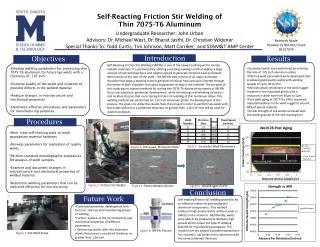
Results • Submerged welds maintained 90-95% of parent UTS • Parent material UTS of 44.88 ksi compared well to the welded plate averaging UTS of ~41 ksi • Worm hole defect welds failed at 65% of parent UTS • effective dry weld equivalent tests not run • Optimal welds for IFSW required a weld pitch increase of 60% • Weld pitch of dry to wet optimal welds • Dry welds: wp = 2000/16 = 125 rev/inch • Wet welds: wp = 2000/10 = 200 rev/inch
Results • Average torque increased from FSW to IFSW • FSW: 16 Nm • SFSW: 18.5 Nm • Elastic Modulus also increases for IFSW when compared to FSW • FSW: 1250 ksi • SFSW: 1450 ksi
Summary and Conclusions • Optimal submerged (wet) FSW’s were compared to conventional dry FSW • Decrease in grain growth in the weld nugget due to inhibition by the fluid (water) • Water welds performed as well if not better than dry welds in tensile tests • Elastic Modulus of the SFSW’s were considerably higher than that of traditional FSW • Leading to a less elastic and therefore less workable material • Dry FSW: E = ~1200 ksi • SFSW: E = ~1400 ksi
Future Work • Fracture Surface Microscopy • Cross section work for electron microscopy • TEM • SEM • Hardness Testing for comparison • Further Mechanical testing • e.g. bend tests
Acknowledgements • This work was supported in part by: • Los Alamos National Laboratory • NASA (GSRP and MSFC) • The American Welding Society • Robin Midgett for materials testing capabilities
References • Thomas M.W., Nicholas E.D., Needham J.C., Murch M.G., Templesmith P., Dawes C.J.:G.B. patent application No. 9125978.8, 1991. • Crawford R., Cook G.E. et al. “Robotic Friction Stir Welding”. Industrial Robot 2004 31 (1) 55-63. • Hofmann D.C. and Vecchio K.S. “Submerged friction stir processing (SFSP): An improved method for creating ultra-fine-grained bulk materials”. MS&E 2005. • Arbegast W. et al. “Friction Stir Spot Welding”. 6th International Symposium on FSW. 2006.