Database Management system
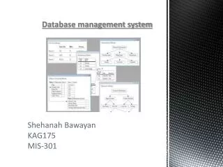
CS 222. Lecture 4. Database Management system. Somchai Thangsathityangkul. University Teaching Database. Design an E-R schema for a database to store info about professors, courses and course sections indicating the following: The name and employee ID number of each professor

Database Management system
E N D
Presentation Transcript
CS 222 Lecture 4 Database Management system SomchaiThangsathityangkul
University Teaching Database Design an E-R schema for a database to store info about professors, courses and course sections indicating the following: • The name and employee ID number of each professor • The salary and email address(es) for each professor • How long each professor has been at the university
University Teaching Database • The course sections each professor teaches • The name, number and topic for each course offered • The section and room number for each course section • Each course section must have only one professor • Each course can have multiple sections
University Teaching Database Design an E-R schema for a database to store info about professors, courses and course sections indicating the following: • The name and employee ID number of each professor • The salary and email address(es) for each professor • How long each professor has been at the university • The course sections each professor teaches
University Teaching Database Design an E-R schema for a database to store info about professors, courses and course sections indicating the following: • The name, number and topic for each course offered • The section and room number for each course section • Each course section must have only one professor • Each professor can teach more than one course and section • Each course can have multiple sections
Entity Course & Section Number: 3753 Name: Database Management Systems Topic: Introduction to DBMSs
Step 1: Model the Entities • In the case of the Order Entry example, there are several candidate entities. The initial analysis of the Order Entry Form indicates that there are three entities that are clearly represented on the form: • ORDER, CUSTOMER, and PRODUCT.
An ORDER ENTRY FORM ORDER CUSTOMER PRODUCT
Step 1: Model the Entities (Cont) • After identifying the entities, we need to decide which attributes to place with each entity. • We must make an assumption on some attribute such as price. • If the price of a product does not change from one order to another, then PRICE is a function of PRODUCT. If, however, different orders for the same product have different prices, then PRICE is a function of the relationship between PRODUCT and ORDER.
Step 2: Choose Primary Keys • After identifying and modeling each entity and its attributes, primary keys must be chosen for each entity. • For each instance of the entity the value of the attribute must be unique and never be null. • Primary key will never changes.
Step 2: Choose Primary Keys (Cont) • Suppose that a database designer decided to make the primary key of the entity CUSTOMER the customer's phone number. • Assume for the moment that each customer has a phone number and that no two customers can have the same phone number. This means unique. • Problem may occur. What happens if a customer changes his or her phone number? • If the primary key value is changed for a record in the CUSTOMER table, related records in other tables must also be changed.
Step 2: Choose Primary Keys (Cont) • When no suitable primary key can be found among the existing attributes for an entity, it is acceptable, and in fact usually a good idea, to simply create a new attribute. • So, we create a CUSTOMER-ID that generating a unique number as a primary key for customer. • So as product, we create a PROD-ID that generating a unique number as a primary key for product. • ORDER-NO is always unique and never change for the order form. We can use ORDER-NO as a primary key for order.
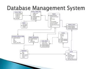
Step 2: Choose Primary Keys (Cont) Now, we draw the initial entities
Step 3: Model Relationships • In the case of the Order Entry Form example, ORDER and CUSTOMER are related because CUSTOMER places an ORDER. As are ORDER and PRODUCT because an ORDER contains PRODUCT. • However, we know that there may not necessarily be a relationship between PRODUCT and CUSTOMER. Because both are related to ORDER we can report which products are ordered by a particular customer.
Step 3: Model Relationships (Cont) We may draw the pair of relationships in matrix table.
Step 3: Model Relationships (Cont) Now , we must identify connectivity of each relationship. 1 M N 1 1 1 M 1
Step 3: Model Relationships (Cont) • We may need to identify cardinality of each relationship. • An ORDER must be related to only one CUSTOMER but CUSTOMER may have many orders or may not have any order. ( 0,N ) ( 1,1 ) ( 1,1 ) ( 0,N )
Step 3: Model Relationships (Cont) It is reasonable to assume that we have products that have not been ordered yet. If this is allowed, then the minimum cardinality from PRODUCT to ORDER is zero. PRODUCT may be in many orders but ORDER must contain at least one product. ( 1,N ) ( 0,N ) ( 1,N ) ( 0,N )
Step 4 - Check the Model • The final step in creating an E-R diagram is often overlooked, but is just as important as any of the previous steps. Analysts who fail to carefully check their ERD often produce diagrams of poor quality, which of course should be avoided. • The basic idea is to go back to the original documents and make sure that the structure represented in the ERD can satisfy the requirements. For example,the representations in the ERD must be able to reproduce any forms or reports required.
Step 4 - Check the Model (Cont) • The designed er model has M:N connectivity and there are some attributes that should be added to the entities such as QTY, EXT, Total. • We can fix M:N connectivity by used composite entity. • Examination of the Order Entry Form shows that there are three items that are not represented on the ERD: EXT, TOTAL, and QTY. Both EXT, which is short for Extended, and TOTAL can be computed, so it is not necessary to store these in the database, or represent them on the ERD.
Step 4 - Check the Model (Cont) • Unlike EXT and TOTAL, QTY (Quantity) can not be computed, and therefore must be stored in the database. Once the analyst decides that QTY should be represented on the ERD, the question becomes how to represent it. • Initial ideas might include representing QTY as an attribute of ORDER, or of PRODUCT. However, QTY is not really an attribute of either of these, but is properly represented as an attribute of the relationship between ORDER and PRODUCT.
Step 4 - Check the Model (Cont) Fixed M:N Connectivity
Step 4 - Check the Model (Cont) Final ERD
Disjoint and Overlapping Constraints • Disjoint subtypes • Also called nonoverlapping subtypes • Subtypes that contain unique subset of supertype entity set • Overlapping subtypes • Subtypes that contain nonunique subsets of supertype entity set
Completeness Constraint • Partial completeness • Symbolized by a circle over a single line • Some supertype occurrences are not members of any subtype • Total completeness • Symbolized by a circle over a double line • Every supertype occurrence must be member of at least one subtype
Fan Traps • Design trap occurs when relationship is improperly or incompletely identified • Represented in a way not consistent with the real world • Most common design trap is known as fan trap • Fan trap occurs when one entity is in two 1:M relationships to other entities • Produces an association among other entities not expressed in the model