Chapter 30 Inductance
Chapter 30 Inductance. Magnetic Effects. As we have seen previously, changes in the magnetic flux due to one circuit can effect what goes on in other circuits The changing magnetic flux induces an emf in the second circuit. Mutual Inductance. Suppose that we have two coils,

Chapter 30 Inductance
E N D
Presentation Transcript
Magnetic Effects • As we have seen previously, changes in the magnetic flux due to one circuit can effect what goes on in other circuits • The changing magnetic flux induces an emf in the second circuit
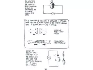
Mutual Inductance Suppose that we have two coils, Coil 1 with N1 turns and Coil 2 with N2 turns Coil 1 has a current i1 which produces a magnetic flux, FB2, going through one turn of Coil 2 If i1 changes, then the flux changes and an emf is induced in Coil 2 which is given by
Mutual Inductance The flux through the second coil is proportional to the current in the first coil where M21 is called the mutual inductance Taking the time derivative of this we get or
Mutual Inductance If we were to start with the second coil having a varying current, we would end up with a similar equation with an M12 We would find that The two mutual inductances are the same because the mutual inductance is a geometrical property of the arrangement of the two coils To measure the value of the mutual inductance you can use either or
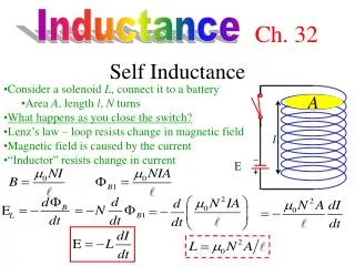
Self Inductance Suppose that we have a coil having N turns carrying a current I That means that there is a magnetic flux through the coil This flux can also be written as being proportional to the current with L being the self inductancehaving the same units as the mutual inductance
Self Inductance If the current changes, then the magnetic flux through the coil will also change, giving rise to an induced emf in the coil This induced emf will be such as to oppose the change in the current with its value given by If the current I is increasing, then If the current I is decreasing, then
Self Inductance There are circuit elements that behave in this manner and they are called inductors and they are used to oppose any change in the current in the circuit As to how they actually affect a circuit’s behavior will be discussed shortly
What Haven’t We Talked About • There is one topic that we have not mentioned with respect to magnetic fields • Just as with the electric field, the magnetic field has energy stored in it • We will derive the general relation from a special case
Magnetic Field Energy When a current is being established in a circuit, work has to be done If the current is i at a given instant and its rate of change is given by di/dt then the power being supplied by theexternal source is given by The energy supplied is given by The total energy stored in the inductor is then
Magnetic Field Energy This energy that is stored in the magnetic field is available to act as source of emf in case the current starts to decrease We will just present the result for the energy density of the magnetic field This can then be compared to the energy density of an electric field
R-L Circuit We are given the following circuit and we then close S1 and leave S2 open It will take some finite amount of time for the circuit to reach its maximum current which is given by Kirchoff’s Law for potential drops still holds
R-L Circuit Suppose that at some time t the current is i The voltage drop across the resistor is given by The magnitude of the voltage drop across the inductor is given by The sense of this voltage drop is that point b is at a higher potential than point c so that it adds in as a negative quantity
But what about the behavior between t = 0 and t = R-L Circuit We take this last equation and solve for di/dt Notice that at t = 0 when I = 0 we have that Also that when the current is no longer changing, di/dt = 0, that the current is given by as expected
R-L Circuit We rearrange the original equation and then integrate The solution for this is Which looks like
R-L Circuit As we had with the R-C Circuit, there is a time constantassociated with R-L Circuits Initially the power supplied by the emf goes into dissipative heating in the resistor and energy stored in the magnetic field After a long time has elapsed, the energy supplied by the emf goes strictly into dissipative heating in the resistor
R-L Circuit We now quickly open S1 and close S2 The current does not immediately go to zero The inductor will try to keep the current, in the same direction, at its initial value to maintain the magnetic flux through it
R-L Circuit Applying Kirchoff’s Law to the bottom loop we get Rearranging this we have and then integrating this where I0 is the current at t = 0
R-L Circuit This is a decaying exponential which looks like The energy that was stored in the inductor will be dissipated in the resistor
L-C Circuit Suppose that we are now given a fully charged capacitor and an inductor that are hooked together in a circuit Since the capacitor is fully charged there is a potential difference across it given by Vc = Q / C The capacitor will begin to discharge as soon as the switch is closed
L-C Circuit We apply Kirchoff’s Law to this circuit Remembering that We then have that The circuit equation then becomes
L-C Circuit This equation is the same as that for the Simple Harmonic Oscillator and the solution will be similar The system oscillates with angular frequency j is a phase angle determined from initial conditions The current is given by
L-C Circuit Both the charge on the capacitor and the current in the circuit are oscillatory The maximum charge and the maximum current occur p / (2w) seconds apart For an ideal situation, this circuit will oscillate forever
L-C Circuit Just as both the charge on the capacitor and the current through the inductor oscillate with time, so does the energy that is contained in the electric field of the capacitor and the magnetic field of the inductor Even though the energy content of the electric and magnetic fields are varying with time, the sum of the two at any given time is a constant
L-R-C Circuit Instead of just having an L-C circuit with no resistance, what happens when there is a resistance R in the circuit Again let us start with the capacitor fully charged with a charge Q0 on it The switch is now closed
L-R-C Circuit The circuit now looks like The capacitor will start to discharge and a current will start to flow We apply Kirchoff’s Law to this circuit and get And remembering that we get
L-R-C Circuit The solution to this second order differential equation is similar to that of the damped harmonic oscillator The are three different solutions Underdamped Critically Damped Overdamped Which solution we have is dependent upon the relative values of R2 and 4L/C
L-R-C Circuit Underdamped: The solution to the second differential equation is then The system still oscillates but with decreasing amplitude, which is represented by the decaying exponential This solution looks like This decaying amplitude is often referred to as the envelope
L-R-C Circuit Critically Damped: Here the solution is given by This solution looks like This is the situation when the system most quickly reaches q = 0
L-R-C Circuit Overdamped: Here the solution has the form This solution looks like with
L-R-C Circuit The solutions that have been developed for this L-R-C circuit are only good for the initial conditions at t = 0 that q = Q0 and that i = 0