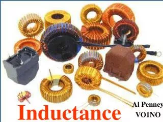
Inductance
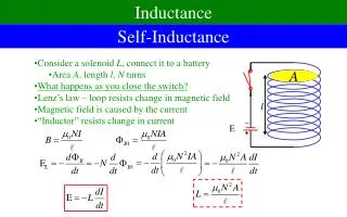
Inductance. Al Penney VO1NO. Inductance. Inductance is the property of an electrical circuit that opposes a change in current. In a DC circuit inductance has an effect only when the DC starts , or when attempts are made to stop it.

Inductance
E N D
Presentation Transcript
Inductance Al Penney VO1NO
Inductance • Inductance is the property of an electrical circuit that opposes a change in current. • In a DC circuit inductance has an effectonly when the DC starts, or when attempts are made to stop it. • In an AC circuit though, the voltage is constantly changing, and inductance constantly works to retard the change in current.
Current Through a Wire • A current through a wire will generate a magnetic field around that wire, as can be demonstrated by bringing a compass near that wire.
No Current Current
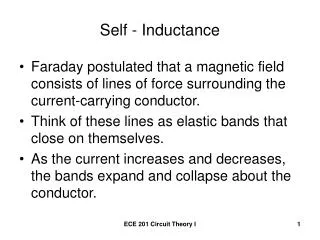
Magnetic Field Effects on a Wire • Conversely, when magnetic lines of flux cut through a wire, a current will be induced to flow in that wire. • This is the basis for generators.
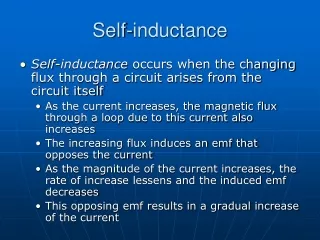
Counter EMF • When a current starts to flow through a wire, it takes a finite time for the magnetic field to build up to its final size. • As the magnetic field builds up, its own lines of flux cut through the conductor. • This induces a voltage and resulting current in that wire. • Because of Conservation of Energy reasons, that induced current opposes the applied current. • This opposing voltage is called the Counter or Back EMF (Electro Motive Force – voltage).
Inductor in a DC Circuit • Counter EMF can only be generated as the magnetic field around a conductor is changing. • After the initial current surge in a DC circuit, the current, and therefore the magnetic field,stabilize and remain steady. • The Counter EMF therefore disappears. • Usually, inductance can be ignored in most DC circuits, however…
Counter EMF Backlash! • In some devices such as electric motors and relays, the Counter EMF can cause problems. • When the device is turned off, the magnetic fieldcollapses, inducing a strong Counter EMF. • This can be strong enough that it can cause an arc in the switch that controls the device. • Sometimes it can even weld the switch shut, restarting the device and making it very difficult to stop.
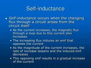
Inductor in an AC Circuit • In an AC circuit, the voltage, and therefore the current, is constantly changing. • Because of this, the magnetic field around the conductor carrying the current is constantly changing as well. • As the magnetic field alternately expands outwards and collapses inwards, the magnetic lines of flux are constantly cutting through the conductor. • This creates a Counter EMF that constantly acts to oppose any change in current.
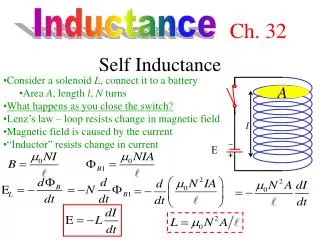
The henry • The unit of measurement for inductance is the henry, abbreviated “L”. • An inductor is said to have an inductance of 1 henry if a current passing through it at a rate of 1 ampere per second causes a Counter EMF of 1 volt to be generated. • This is too large a unit for most applications however, so millihenrys (mh) or microhenrys (μh) are more commonly encountered in electronic equipment.
Factors Affecting Inductance • Number of Turns: The inductance of a coil is proportional to the square of the number of turns. • A coil with twice the number of turns as another otherwise identical coil will have four times the inductance. A coil with 3 times as many turns will have 9 times the inductance.
Factors Affecting Inductance • Coil Diameter: The larger the diameter of the coil, the greater the inductance. • A coil with twice the diameter of an otherwise identical coil will have twice the inductance.
Factors Affecting Inductance • Changing the core: Certain materials will concentrate the lines of magnetic flux better than others, and will therefore increase the inductance if used as a core for the coil. • For example, a coil wound on an iron core will have much more inductance than one with an air core.
Example - Inductors in Series 8 henry Ltotal = L1 + L2 + L3 Ltotal= 8H + 10H + 22H Ltotal = 40 H 10 henry 22 henry
Example - Inductors in Parallel Ltotal = 1 1 + 1 + 1 10 15 30 Ltotal = 1 = 3 + 2 + 1 30 30 30 10H 15H 30H 1 = 5H 6/30
Reactance • Reactance is the opposition to the flow of Alternating Current (AC). • Reactance has no effect on the flow of Direct Current (DC).
Inductive Reactance • Inductive Reactance is the opposition to the flow of current in an AC circuit caused by an inductor. • As the frequency increases, Inductive Reactance also increases. • The symbol for Inductive Reactance is XL. • Even though it is expressed in ohms, power is not dissipated by Reactance! Energy stored in an inductor’s magnetic field during one part of the AC cycle is simply returned to the circuit during the next part of the cycle!
Inductive Reactance • Where: f = frequency in Hertz L = inductance in henrys π = 3.14
Inductive Reactance Example 1 • What is the reactance of a coil having an inductance of 8.00 henrys at a frequency of 120 Hertz? XL = 2 x 3.14 x 120 Hertz x 8.00H XL = 6030 Ohms
Inductive Reactance Example 2 • What is the reactance of that same coil having an inductance of 8.00 henrys at a frequency of 2 kHz? Remember that 2 kHz = 2000 Hz XL = 2 x 3.14 x 2000 Hertz x 8.00H XL = 100,480 Ohms
Inductive Reactance Examples • Note that as the frequency increased from 120 Hz to 2000 Hz, the Inductive Reactance increased from 6030 ohms to 100,480 ohms. • Remember: • Inductors allow DC to pass, but hinder AC; • Inductors store energy as a magnetic field; and • As the frequency increases,inductive reactance increases (and vice versa!).
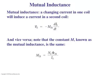
Transformers • Any device that transfers power from one voltage-current level to another voltage-current level is called a transformer. • Transformers work on the principle of changing current in one inductor inducing a current in another inductor.
Transformer Applications • Transformers have 3 primary applications: • Isolating one part of a circuit from another (magnetic linkage only, versus conductive linkage); • Steppingvoltages up or down; and • Impedance matching.
Isolation Transformer • Many uses for isolation transformers in electronic circuits. • Also used in power circuits, using transformers that have a 1:1 turns ratio.
Changing the Voltage • A transformer can be used to step the voltage up or down. • The ratio of turns in the primary and secondary windings determine the amount of voltage change: Primary Voltage # Turns Primary winding Secondary Voltage # Turns Secondary winding =
Example • Input voltage is 120 VAC. You require an output voltage of 24 VAC. The Primary winding has 240 turns. How many turns does the Secondary winding need?
Example (2) Primary Voltage # Turns Primary winding Secondary Voltage # Turns Secondary winding =
Example (3) Primary Voltage # Turns Primary winding Secondary Voltage # Turns Secondary winding • 120 / 24 = 240 / Tsec • Tsec = =
Example (4) Primary Voltage # Turns Primary winding Secondary Voltage # Turns Secondary winding • 120 / 24 = 240 / Tsec • Tsec = 240 x 24 / 120 =
Example (5) Primary Voltage # Turns Primary winding Secondary Voltage # Turns Secondary winding • 120 / 24 = 240 / Tsec • Tsec = 240 x 24 / 120 • Tsec = =
Example (6) Primary Voltage # Turns Primary winding Secondary Voltage # Turns Secondary winding • 120 / 24 = 240 / Tsec • Tsec = 240 x 24 / 120 • Tsec = 48 turns =