Download
1 / 23
270 likes | 598 Vues
Self-Inductance. AP Physics C Montwood High School R. Casao. Resistance, Capacitance, & Inductance. Ohm’s law defines resistance as: Resistors do not store energy; they transform electrical energy into thermal energy at a rate of: Capacitance is the ability to hold charge:

E N D
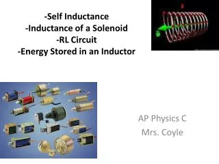
Self-Inductance AP Physics C Montwood High School R. Casao
Resistance, Capacitance, & Inductance • Ohm’s law defines resistance as: • Resistors do not store energy; they transform electrical energy into thermal energy at a rate of: • Capacitance is the ability to hold charge: • Capacitors store electric energy in the electric field between the plates when fully charged:
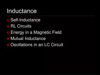
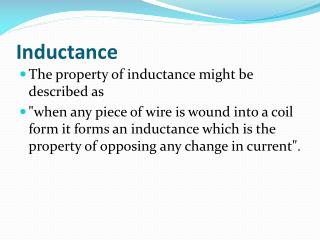
Inductance can be described as the ability to “hold” current. • Inductors store energy in the magnetic field inside the inductor once the current flows through it. Terminology: • EMF and current are associated with batteries or other primary voltage sources. • Induced EMF and induced current are associated with changing magnetic flux.
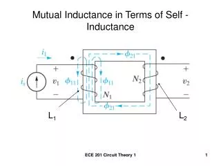
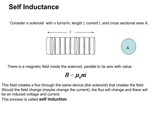
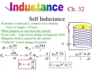
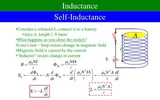
Inductance, the definition When a current flows through a coil, there is magnetic field established. If we take the solenoid assumption for the coil: I + EL E When this magnetic field flux changes, it induces an emf, EL, called self-induction: – Where n= # of turns per unit length. N = # of turns in length l. A = cross section area V = Volume for length l. For a solenoid: Inductance L, is a constant related only to the coil. The self-induced emf εL is generated by (changing) current in the coil. According to Lenz’s Law, the emf generated inside this coil is always opposing the change of the current which is delivered by the original emf ε.
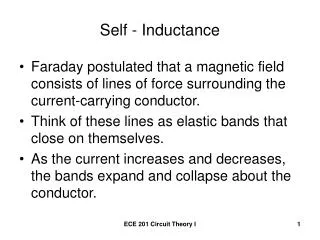
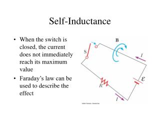
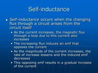
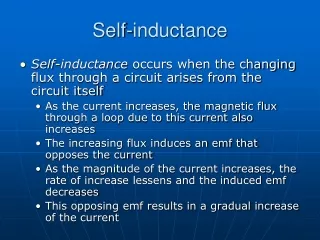
Consider an isolated circuit consisting of a switch, a resistor, and a source of EMF. • When the switch is closed, the current doesn’t immediately jump from zero to its maximum value,
The law of electromagnetic induction (Faraday’s law) prevents this from happening. • As the current increases with time, the magnetic flux through the loop due to this current also increases with time.
The increasing flux induces an EMF in the circuit that opposes the change in the net magnetic flux through the loop. • By Lenz’s law, the induced electric field in the wires must be opposite to the direction of the conventional current and the opposing EMF and the induced current that results establishes a magnetic field that opposes the change in the source magnetic field.
The direction of the induced EMF is opposite the direction of the source EMF; this results in a gradual rather than instantaneous increase in the source current to its final equilibrium value. • This effect is called self-induction since the changing flux through the circuit arises from the circuit itself. • The EMF, EMFL, that is set up in this case is called a self-induced EMF or back EMF. • Faraday’s law tells us that the induced EMF is the negative time rate of change of the magnetic flux.
The magnetic flux is proportional to the magnetic field, which is proportional to the current in the circuit. • Therefore, the self-induced EMF is always proportional to the time rate of change of the current. • For a closely spaced coil of N turns of fixed geometry (a toroidal coil or a solenoid): • where L is a proportionality constant, called the inductance of the device, that depends on the geometric features of the circuit and other physical characteristics.
Remember: the minus sign is a reflection of Lenz’s law; it says that the self-induced EMF in a circuit opposes any change in the current in that circuit. • The inductance of a coil containing N turns is: • where it is assumed that the same flux passes through each turn. • Inductance can also be rewritten as the ratio:
- This is usually taken to be the defining equation for the inductance of any coil, regardless of its shape, size, or material characteristics. • Just as resistance is a measure of the opposition to current, inductance is a measure of the opposition to the change in current. • Inductance unit: henry (H); • The inductance of a device depends on its geometry, much like the capacitance of a capacitor depended on the geometry of its plates.
Consider a coil wound on a cylindrical iron core and that the source current in the coil either increases or decreases with time. • When the source current is in the direction shown (figure a), a magnetic field directed from right to left is set up inside the coil.
As the source current changes with time, the magnetic flux through the coil also changes and induces an EMF in the coil. • From Lenz’s law, the polarity of this induced EMF must be such that it opposes the change in the magnetic field from the source current.
If the source current is increasing, the polarity of the induced EMF is as shown in figure b. • If the source current is decreasing, the polarity of the induced EMF is as shown in figure c.
Many problems will ask you to identify the point on either side of an inductor that has the higher potential. • To determine which point is at the higher potential, curl the fingers of your right hand in the direction of the induced current within the inductor; the right thumb points in the direction of the point which is at the higher potential. • The point on either side of an inductor that is at the higher potential is the point that is in the direction of the Binduced vector.
Inductance of a Solenoid • Find the inductance of a uniformly wound solenoid with N turns and length l that is long compared with the radius and that the core of the solenoid is air. • The magnetic field of the solenoid is: • The magnetic flux through each turn is: • where A is the cross-sectional area of the solenoid.
Inductance: • This shows that L depends on geometric factors and is proportional to the square of the number of turns. • Since n = N/l, and N = n·l:
Calculating Inductance and EMF • Calculate the inductance of a solenoid containing 300 turns if the length of the solenoid is 25 cm and its cross-sectional area is 0.0004 m2.
Calculate the self-induced (back) EMF in the solenoid described if the current through it is decreasing at a rate of 50 A/s. • dI/dt is negative because the rate of change is decreasing.
The potential difference across a resistor depends on the current. • Resistor with current i flowing from a to b; potential drops from a to b. • The potential difference across an inductor depends on the rate of change of the current. • Inductor with constant current i flowing from a to b; no potential difference.
Inductor with increasing current I flowing from a to b; potential drops from a to b. • Inductor with decreasing current I flowing from a to b; potential increases from a to b.
Inductors in Series and in Parallel • Inductors, like resistors and capacitors, can be placed in series. • Total inductance can be increased by placing inductors in series. LT = L1 + L2 + L3 + . . . + LN
Inductors in Series and in Parallel • Inductors, like resistors and capacitors, can be placed in parallel. • Total inductance can be decreased by placing inductors in parallel.