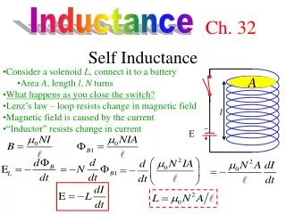
Self-inductance
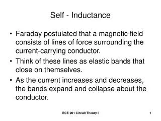
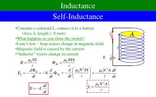
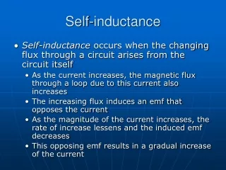
Self-inductance. Self-inductance occurs when the changing flux through a circuit arises from the circuit itself As the current increases, the magnetic flux through a loop due to this current also increases The increasing flux induces an emf that opposes the current

Self-inductance
E N D
Presentation Transcript
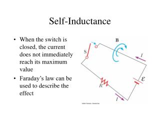
Self-inductance • Self-inductance occurs when the changing flux through a circuit arises from the circuit itself • As the current increases, the magnetic flux through a loop due to this current also increases • The increasing flux induces an emf that opposes the current • As the magnitude of the current increases, the rate of increase lessens and the induced emf decreases • This opposing emf results in a gradual increase of the current
Self-inductance cont • The self-induced emf must be proportional to the time rate of change of the current • L is a proportionality constant called the inductance of the device • The negative sign indicates that a changing current induces an emf in opposition to that change
Self-inductance, final • The inductance of a coil depends on geometric factors • The SI unit of self-inductance is the Henry • 1 H = 1 (V · s) / A
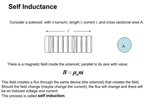
http://www.bugman123.com/Physics/Physics.html For infinitely long solenoid B = monI n: number of turns/m
L: self inductance [L] = Henry Winding density: n Loop area: A Length of coil: ℓ Increase current through the coil from 0 to di in dt. Causes flux change for each loop from F = 0 to F = AB where B = mondi Vind = - n ℓdF/dt = - n ℓA(mon)di/dt = - n2moA ℓ (di/dt) Purely geometrical quantity
r = 1 cm ℓ = 2.5 cm n = 10 turns/cm = 0.01 m = 0.025 m = 1000 turns/m L = n2moA ℓ = (1000)2(4 p x 10-7)(p x 0.0012)0.025 = 9.9 x 10⁻⁶ H = 9.9 mH
Example 24.5 A steady current of 5.0 A is flowing through a coil with 2 H Self inductance. The current is suddenly stopped in 0.01 s. How large an emf induced in the coil? Vind = -L (di/dt) = - (2.0) (-5/0.01) = 1000 V Di = if – ii = -5 A
Inductors in an AC Circuit • Consider an AC circuit with a source and an inductor • The current in the circuit is impeded by the back emf of the inductor • The voltage across the inductor always leads the current by 90° (T/4)
V v A AC i lags 90 deg behind v. i v= vosin(wt) v = -L di/dt i = -io cos(wt) vo = wLio vosin(wt) = wLiosin(wt)
Inductive Reactance and Ohm’s Law • The effective resistance of a coil in an AC circuit is called its inductive reactance and is given by • XL = L=2ƒL • When ƒ is in Hz and L is in H, XL will be in ohms • Ohm’s Law for the inductor • V = I XL
Inductor in a Circuit • Inductance can be interpreted as a measure of opposition to the rate of change in the current • Remember resistance R is a measure of opposition to the current • As a circuit is completed, the current begins to increase, but the inductor produces an emf that opposes the increasing current • Therefore, the current doesn’t change from 0 to its maximum instantaneously
RL Circuit • When the current reaches its maximum, the rate of change and the back emf are zero • The time constant, , for an RL circuit is the time required for the current in the circuit to reach 63.2% of its final value
RL Circuit, cont • The time constant depends on R and L • The current at any time can be found by
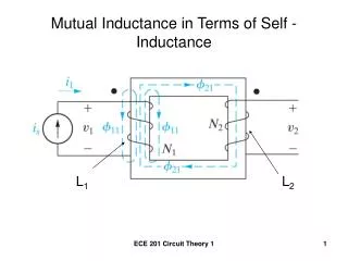
M21 Mutual inductance To ch. circuit AC Transformer Iron Core V2 = - (di1/dt) i1 N1 N2
The RLC Series Circuit • The resistor, inductor, and capacitor can be combined in a circuit • The current in the circuit is the same at any time and varies sinusoidally with time
Current and Voltage Relationships in an RLC Circuit • The instantaneous voltage across the resistor is in phase with the current • The instantaneous voltage across the inductor leads the current by 90° • The instantaneous voltage across the capacitor lags the current by 90°
VL VC VR v = vc + vL + vR i= iosin(wt) i A i= iosin(wt) vo = Xio vR Rio sin(wt) AC wLio cos(wt) vL i lags 90 deg behind v. - cos(wt) (1/wC)io vC V lags 90 deg behind i.
vo = Xio RLC Series Resonance Circuit v = vc + vL + vR = -(1/wC)io cos(wt) + wLio cos(wt) + Rio sin(wt) = {(wL-1/wC)io} cos(wt) + Rio sin(wt) = {(wL-1/wC)2 + R2}1/2(io) sin(wt+q) XRLC Resonance: wL = 1/wC XRLC = {(wL-1/wC)2 + R2}0.5 io = vo/XRLC R w w = 1/(LC)0.5
V RLC Parallel Resonance Circuit vo A i= iosin(wt) AC w = 1/(LC)0.5
Power in an AC Circuit • No power losses are associated with capacitors and pure inductors in an AC circuit • In a capacitor, during one-half of a cycle energy is stored and during the other half the energy is returned to the circuit • In an inductor, the source does work against the back emf of the inductor and energy is stored in the inductor, but when the current begins to decrease in the circuit, the energy is returned to the circuit
Power in an AC Circuit, cont • The average power delivered by the generator is converted to internal energy in the resistor • Pav = IVR = IV cos • cos is called the power factor of the circuit • Phase shifts can be used to maximize power outputs
Resonance in an AC Circuit • Resonance occurs at the frequency, ƒo, where the current has its maximum value • To achieve maximum current, the impedance must have a minimum value • This occurs when XL = XC
Resonance, cont • Theoretically, if R = 0 the current would be infinite at resonance • Real circuits always have some resistance • Tuning a radio • A varying capacitor changes the resonance frequency of the tuning circuit in your radio to match the station to be received • Metal Detector • The portal is an inductor, and the frequency is set to a condition with no metal present • When metal is present, it changes the effective inductance, which changes the current which is detected and an alarm sounds
Simple Radio http://www.tricountyi.net/~randerse/xtal.htm
James Clerk Maxwell • Electricity and magnetism were originally thought to be unrelated • in 1865, James Clerk Maxwell provided a mathematical theory that showed a close relationship between all electric and magnetic phenomena
Maxwell’s Starting Points • Electric field lines originate on positive charges and terminate on negative charges • Magnetic field lines always form closed loops – they do not begin or end anywhere • A varying magnetic field induces an emf and hence an electric field (Faraday’s Law) • Magnetic fields are generated by moving charges or currents (Ampère’s Law)
Maxwell’s Predictions • Maxwell used these starting points and a corresponding mathematical framework to prove that electric and magnetic fields play symmetric roles in nature • He hypothesized that a changing electric field would produce a magnetic field • Maxwell calculated the speed of light to be 3x10⁸ m/s • He concluded that visible light and all other electromagnetic waves consist of fluctuating electric and magnetic fields, with each varying field inducing the other
Hertz’s Confirmation of Maxwell’s Predictions • Heinrich Hertz was the first to generate and detect electromagnetic waves in a laboratory setting
James Clerk Maxwell’s Equations (1867) E-field comes out from p-charge and terminates at negative charge. Pre-Maxwell B-field cannot do like E-field. No magnetic monopole! Faraday’s law Ampere’s law
The velocity of transverse undulations in our hypothetical medium, calculated from the electromagnetic experiments, agrees so exactly with the velocity of light calculated from the optical experiments, that we can scarcely avoid the inference that light consists in the transverse undulation of same medium which is the cause of electric and magnetic Phenomena. 2.9986 x 10⁸ m/s
Hertz’s Experiment (1887)
Hertz’s Basic LC Circuit • When the switch is closed, oscillations occur in the current and in the charge on the capacitor • When the capacitor is fully charged, the total energy of the circuit is stored in the electric field of the capacitor • At this time, the current is zero and no energy is stored in the inductor
LC Circuit, cont • As the capacitor discharges, the energy stored in the electric field decreases • At the same time, the current increases and the energy stored in the magnetic field increases • When the capacitor is fully discharged, there is no energy stored in its electric field • The current is at a maximum and all the energy is stored in the magnetic field in the inductor • The process repeats in the opposite direction • There is a continuous transfer of energy between the inductor and the capacitor
Hertz’s Experimental Apparatus • An induction coil is connected to two large spheres forming a capacitor • Oscillations are initiated by short voltage pulses • The inductor and capacitor form the transmitter
Hertz’s Experiment • Several meters away from the transmitter is the receiver • This consisted of a single loop of wire connected to two spheres • It had its own inductance and capacitance • When the resonance frequencies of the transmitter and receiver matched, energy transfer occurred between them
Hertz’s Conclusions • Hertz hypothesized the energy transfer was in the form of waves • These are now known to be electromagnetic waves • Hertz confirmed Maxwell’s theory by showing the waves existed and had all the properties of light waves • They had different frequencies and wavelengths