Download
1 / 23
241 likes | 1.7k Vues
Learn about mutual inductance, self-inductance, energy storage in magnetic fields, LR circuits, LC circuits, and LRC circuits with practical examples and calculations.

E N D
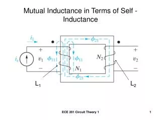
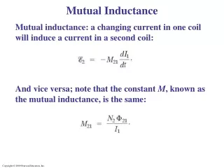
Mutual Inductance Mutual inductance: a changing current in one coil will induce a current in a second coil: And vice versa; note that the constant M, known as the mutual inductance, is the same:
Mutual Inductance Unit of inductance: the henry, H: 1 H = 1 V·s/A = 1 Ω·s. A transformer is an example of mutual inductance.
Mutual Inductance Example A long thin solenoid of length l and cross-sectional area A contains N1 closely packed turns of wire. Wrapped around it is an insulated coil of N2 turns. Assume all the flux from coil 1 (the solenoid) passes through coil 2, and calculate the mutual inductance.
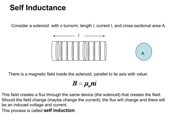
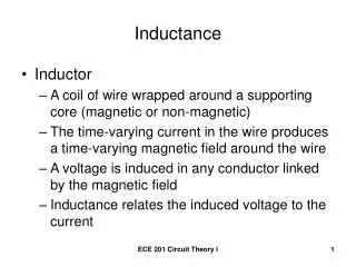
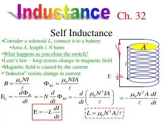
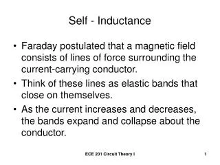
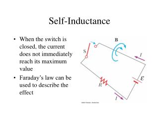
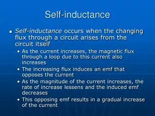
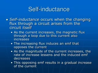
Self-Inductance A changing current in a coil will also induce an emf in itself: Here, L is called the self-inductance:
Example Solenoid inductance. (a) Determine a formula for the self-inductance L of a tightly wrapped and long solenoid containing N turns of wire in its length l and whose cross-sectional area is A. (b) Calculate the value of L if N = 100, l = 5.0 cm, A = 0.30 cm2, and the solenoid is air filled.
Self-Inductance Conceptual Example: Direction of emf in inductor. Current passes through a coil from left to right as shown. (a) If the current is increasing with time, in which direction is the induced emf? (b) If the current is decreasing in time, what then is the direction of the induced emf?
Self-Inductance Example: Coaxial cable inductance. Determine the inductance per unit length of a coaxial cable whose inner conductor has a radius r1 and the outer conductor has a radius r2. Assume the conductors are thin hollow tubes so there is no magnetic field within the inner conductor, and the magnetic field inside both thin conductors can be ignored. The conductors carry equal currents I in opposite directions.
Energy Stored in a Magnetic Field Just as we saw that energy can be stored in an electric field, energy can be stored in a magnetic field as well, in an inductor, for example. Analysis shows that the energy density of the field is given by
LR Circuits A circuit consisting of an inductor and a resistor will begin with most of the voltage drop across the inductor, as the current is changing rapidly. With time, the current will increase less and less, until all the voltage is across the resistor.
LR Circuits . . The sum of potential differences around the loop gives Integrating gives the current as a function of time: The time constant of an LR circuit is .
LR Circuits . If the circuit is then shorted across the battery, the current will gradually decay away:
LR Circuits Example 30-6: An LR circuit. At t = 0, a 12.0-V battery is connected in series with a 220-mH inductor and a total of 30-Ω resistance, as shown. (a) What is the current at t = 0? (b) What is the time constant? (c) What is the maximum current? (d) How long will it take the current to reach half its maximum possible value? (e) At this instant, at what rate is energy being delivered by the battery, and (f) at what rate is energy being stored in the inductor’s magnetic field?
LC Circuits and Electromagnetic Oscillations An LC circuit is a charged capacitor shorted through an inductor.
Circuits and Electromagnetic Oscillations . Summing the potential drops around the circuit gives a differential equation for Q: This is the equation for simple harmonic motion, and has solutions .
Circuits and Electromagnetic Oscillations Substituting shows that the equation can only be true for all times if the frequency is given by The current is sinusoidal as well:
LC Circuits and Electromagnetic Oscillations The charge and current are both sinusoidal, but with different phases.
LC Circuits and Electromagnetic Oscillations The total energy in the circuit is constant; it oscillates between the capacitor and the inductor:
LC Circuits and Electromagnetic Oscillations Example: LC circuit. A 1200-pF capacitor is fully charged by a 500-V dc power supply. It is disconnected from the power supply and is connected, at t = 0, to a 75-mH inductor. Determine: (a) the initial charge on the capacitor; (b) the maximum current; (c) the frequency f and period T of oscillation; and (d) the total energy oscillating in the system.
LC Oscillations with Resistance (LRC Circuit) Any real (nonsuperconducting) circuit will have resistance.
LC Oscillations with Resistance (LRC Circuit) Now the voltage drops around the circuit give The solutions to this equation are damped harmonic oscillations. The system will be underdamped for R2 < 4L/C, and overdamped for R2 > 4L/C. Critical damping will occur when R2 = 4L/C.
LC Oscillations with Resistance (LRC Circuit) This figure shows the three cases of underdamping, overdamping, and critical damping.
LC Oscillations with Resistance (LRC Circuit) . . The angular frequency for underdamped oscillations is given by The charge in the circuit as a function of time is
Oscillations with Resistance (LRC Circuit) Example: Damped oscillations. At t = 0, a 40-mH inductor is placed in series with a resistance R = 3.0 Ω and a charged capacitor C = 4.8 μF. (a) Show that this circuit will oscillate. (b) Determine the frequency. (c) What is the time required for the charge amplitude to drop to half its starting value? (d) What value of R will make the circuit nonoscillating?