Download
1 / 17
170 likes | 264 Vues
Discusses approaches to balancing performance and lengthening the 1st and 2nd IR beam delivery systems for the American Linear Collider Workshop in 2003. Analyzes challenges in IR layout evolution and optimization for luminosity and energy reach.

E N D
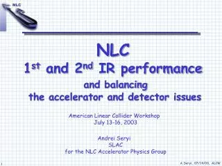
NLC1st and 2nd IR performanceand balancing the accelerator and detector issues American Linear Collider WorkshopJuly 13-16, 2003 Andrei SeryiSLACfor the NLC Accelerator Physics Group
A. Drozhdin, L. Keller, T. Markiewicz, T. Maruyama, N. Mokhov, Yu. Nosochkov, T. Raubenheimer, A. Seryi, P. Tenenbaum, M. Woodley
1st and 2nd IR design approach • Would like to make 1st & 2nd IRs more equivalent, at least up to 1.3TeV CM • Require that Lumi of two IRs can be equal within 30% • The two IRs will never be equal • 1st IR has higher potential (straight tunnel, => multi TeV) • 2nd IR needs big bend => BDS is shorter => lower energy reach • Luminosity loss in FF scales as dL/L~ g7/4 / L5/2. That means that though the required FF length scales only as L ~ g7/10 , the luminosity loss can be significant when the FF length is decreased • => Want to make 1st and 2nd IR BDS as close in length as possible
1st and 2nd IR layout evolution • Evolution of IR layout is driven by attempts to solve this contradiction: • Need 2nd IR BDS to be as close to the “full length” as possible • Need to limit the emittance growth in 2nd IR big bend • This drives the big bend length up, and appear to contradict the previous …
NLC layoutevolution IP2 e+ e- May 03: 1st IR : full length (1430m) BDS 2nd IR : 2/3 length (970m) BDS Big Bend has to be long (600m) so that de/e<30% @ 650 GeV/beam 2nd IR : 2/3 length one way bending BDS Big Bend shortened twice Saved 125m in e- and 450m in e+ beamlines of 2nd IR Lengthen the e+ 2nd IR BDS to full lengthThe e- 2nd IR BDS is still 2/3 length IP1 June 03: e+ e- July 03:
Picture is still June layout e- e+ 970m BDS(will be 1100m) 1400m BDS IP2 1400m BDS 1400m BDS IP1 Full length BDS (1430m) in 1st IR and in e+ side of 2nd IR Only the e- side of 2nd IR has shorter BDS (presently 970m optics, but have space to lengthen it to 1100m) Optics for July 03 layout
BDS performance (July layout)1st and 2nd IR The e- 2nd IR BDS can still be lengthened to improve performance LO~E Geometric luminosity (normalized) of NLC BDS. Include effect of aberration and synchrotron radiation. Beam-beam enhancement is not included. Same normalized emittances assumed for the entire range.
lengthening of 2nd IR e- BDS to 1100m will pull it up somewhat BDS performance (July)in absolute units Geometric luminosity for NLC BDS (optics only: include aberrations and synch.radiation; beam-beam luminosity enhancement is not included). Same normalized emittances assumed for the entire range.
FF upgrade means (1):reduce bending angle in FF E-Collimationbends: Increase angle by 15% To reduce synch.radiation in FF magnets: Reduce bending angle in FF twice, and increase bending angle in E-Collimation by ~15%. Location of IP is fixed. BDS magnets need to be moved by ~20cm. Outgoing angle change by ~1.6 mrad FF bends: reduce angle twice IP One way bending BDS for 2nd IR “Standard” (two way bending) BDS
FF upgrade means (2):use longer Final Doublet Longer FD allow to reduce luminosity degradation due to synch.radiation in FD (Oide effect). Short FD Long FD 2nd IR FD optimized for 90-650 GeV CM range 2nd IR FD optimized for the energy upgrade
BDS performance (July)Benefits of the FF upgrade When luminosity loss is so high at low E, it can be partly regained by increasing b* Geometric luminosity (normalized). Thin curves show performance if upgrade (=layout & FD change) was not made, or if one goes back from 1TeV to Z
SR emitted by halo is lost only on dedicated masks, and do not touch vertex detector. K=1 K>1 FD aperture K=1 corresponds to nominal collimation depth when SR from the halo do not touch the vertex detector Collimation in NLC BDS Octupole Doublets BetatronCollimation EnergyCollimation Collimation system removes the beam halo. Losses of halo occur in dedicated places. No losses after last FF collimator. Assumed halo is 0.1% of the beam Entrance IP
collimator Collimation gaps • Collimation gaps are defined by requirement to protect Vertex Detector from synchrotron radiation emitted by beam halo For a given optics design, gaps are proportional to the Vertex Radius (and are independent on beam energy) • Smallest spoiler gaps in NLC BDS are +-0.2mm (or +-0.6mm with tail folding octupoles)
NLC spoiler is tapered to reduce wake-fields Collimation gaps and wakes Small gaps is an issue (TRC R3) because collimator wakes cause the IP beam jitter to increase For NLC Ab~1.3 (or 0.7 with Octupoles) that means that Y-jitter increase by 64% (or 22% with Octupoles) at 500GeV CM Jitter amplification in y-plane (due to y’) is (1+ Ab2)0.5 times The 22% number would be OK at 500 GeV CM, however, the effect scales as 1/Energy At 90 GeV CM, will have Ab ~ 7 (or Ab ~ 3.9 with octupoles). Unacceptable. • Since Ab almost does not depend on optics, have only three choices: • Solution 0: Ongoing studies will prove that the wake formula give an overestimate • Solution 1: Degrade b* and Luminosity expectations at low E • Solution 2: Increase the vertex detector radius
Possible reduction of luminosity due to collimation wakes Assume that tolerable Ab is 0.7 (or 1.4), which gives 22% (or 72%) Y-jitter increase Luminosity reduction at Z is 2.5 times (or 1.7 times) For Rvx X 2, the reduction is 1.4 times (or none) This assumes the tail folding Octupoles are ON (more optimistic case) Ideal : Lumi ~ g Assumed that for typical spoilers, Abscales as Ab ~ b N / ( sz1/2g gap3/2 ) or, equivalently, as
Vertex radius discussion* Agreed that VX radius is, in certain extents, a free parameter that accelerator physicists can optimize *) This discussion took place in a context of 500GeV CM. The low energy requirements need to be discussed again From studies by Aaron Chou
Conclusion • Performance of NLC BDS optics will allow almost equal luminosities in 1st and 2nd IR up to 1.3 TeV CM • There are potential limitations at Z energy due to collimation wake fields, which need to be taken into account when detector parameters are to be chosen