Download
1 / 39
390 likes | 552 Vues
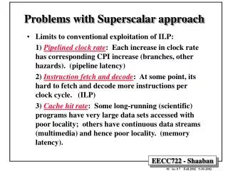
Tiered-Latency DRAM: A Low Latency and A Low Cost DRAM Architecture. Donghyuk Lee, Yoongu Kim, Vivek Seshadri , Jamie Liu , Lavanya Subramanian, Onur Mutlu. Executive Summary. Problem : DRAM latency is a critical performance bottleneck

E N D
Tiered-Latency DRAM:A Low Latency and A Low Cost DRAM Architecture Donghyuk Lee, Yoongu Kim, VivekSeshadri, Jamie Liu, Lavanya Subramanian, OnurMutlu
Executive Summary • Problem: DRAM latency is a critical performance bottleneck • Our Goal: Reduce DRAM latency with low area cost • Observation: Long bitlines in DRAM are the dominant source of DRAM latency • Key Idea: Divide long bitlines into two shorter segments • Fast and slow segments • Tiered-latency DRAM: Enables latency heterogeneity in DRAM • Can leverage this in many ways to improve performance and reduce power consumption • Results: When the fast segment is used as a cache to the slow segment Significant performance improvement (>12%) and power reduction (>23%) at low area cost (3%)
Outline • Motivation & Key Idea • Tiered-Latency DRAM • Leveraging Tiered-Latency DRAM • Evaluation Results
Historical DRAM Trend 16X -20% DRAM latency continues to be a critical bottleneck
What Causes the Long Latency? DRAM Chip DRAM Chip cell array subarray Subarray I/O I/O I/O channel channel DRAM Latency = Subarray Latency + I/O Latency DRAM Latency = Subarray Latency + I/O Latency Dominant
Why is the SubarraySo Slow? Subarray Cell cell wordline access transistor Bitline: 512 cells capacitor bitline Row decoder Sense amplifier extremely large sense amplifier (≈100X the cell size) Long Bitline: Amortize sense amplifier → Small area Long Bitline: Large bitline cap. → High latency
Trade-Off: Area (Die Size) vs. Latency Long Bitline Short Bitline Faster Smaller Trade-Off: Area vs. Latency
Trade-Off: Area (DieSize) vs. Latency 32 Fancy DRAM Short Bitline Commodity DRAM Long Bitline 64 Cheaper 128 256 512 cells/bitline GOAL Faster
Approximating the Best of Both Worlds Long Bitline Short Bitline Long Bitline Our Proposal Short Bitline Large Area Small Area Small Area High Latency Low Latency Low Latency Need Isolation Add Isolation Transistors Short Bitline Fast
Approximating the Best of Both Worlds Long Bitline Short Bitline Long Bitline Tiered-Latency DRAM Our Proposal Short Bitline Large Area Small Area Small Area High Latency Low Latency Low Latency Small area using long bitline Low Latency
Outline • Motivation & Key Idea • Tiered-Latency DRAM • Leveraging Tiered-Latency DRAM • Evaluation Results
Tiered-Latency DRAM Far Segment Isolation Transistor Near Segment Sense Amplifier Divide a bitline into two segments with an isolation transistor
Near Segment Access Reduced bitline length Reduced bitline capacitance Far Segment Low latency & low power Far Segment Isolation Transistor (off) Isolation Transistor Near Segment Sense Amplifier Turn off the isolation transistor
Far Segment Access Long bitline length Large bitline capacitance Additional resistance of isolation transistor High latency & high power Far Segment Isolation Transistor (on) Isolation Transistor Near Segment Sense Amplifier Turn on the isolation transistor Near Segment
Latency, Power, and Area Evaluation • Commodity DRAM: 512 cells/bitline • TL-DRAM: 512 cells/bitline • Near segment: 32 cells • Far segment: 480 cells • Latency Evaluation • SPICE simulation using circuit-level DRAM model • Power and Area Evaluation • DRAM area/power simulator from Rambus • DDR3 energy calculator from Micron
Commodity DRAM vs. TL-DRAM • DRAM Latency (tRC) • DRAM Power +49% +23% (52.5ns) Power Latency –56% –51% Near Far Near Far Commodity DRAM Commodity DRAM TL-DRAM TL-DRAM • DRAM Area Overhead ~3%: mainly due to the isolation transistors
Latency vs. Near Segment Length Latency (ns) Longer near segment length leads to higher near segment latency
Latency vs. Near Segment Length Latency (ns) Far Segment Length = 512 – Near Segment Length Far segment latency is higher than commodity DRAM latency
Trade-Off: Area (Die-Area) vs. Latency 32 64 Cheaper 128 256 512 cells/bitline Near Segment Far Segment GOAL Faster
Outline • Motivation & Key Idea • Tiered-Latency DRAM • Leveraging Tiered-Latency DRAM • Evaluation Results
Leveraging Tiered-Latency DRAM • TL-DRAM is a substrate that can be leveraged by the hardware and/or software • Many potential uses • Use near segment as hardware-managed inclusive cache to far segment • Use near segment as hardware-managed exclusive cache to far segment • Profile-based page mapping by operating system • Simply replace DRAM with TL-DRAM
Near Segment as Hardware-Managed Cache TL-DRAM far segment subarray main memory near segment cache sense amplifier I/O channel Challenge 1: How to efficiently migrate a row between segments? Challenge 2: How to efficiently manage the cache?
Inter-Segment Migration • Naïve way: Memory controller reads the source row byte by byte and writes to destination row byte by byte → High latency Source Far Segment Isolation Transistor Destination Near Segment Sense Amplifier Goal: Migrate source row into destination row
Inter-Segment Migration Source Far Segment Isolation Transistor Destination Near Segment Sense Amplifier • Our way: • Source and destination cells share bitlines • Transfer data from source to destination across shared bitlines concurrently
Inter-Segment Migration Step 1: Activate source row Migration is overlapped with source row access Additional ~4ns over row access latency Far Segment Step 2: Activate destination row to connect cell and bitline Isolation Transistor Near Segment Sense Amplifier • Our way: • Source and destination cells sharebitlines • Transfer data from source to destination across shared bitlines concurrently
Near Segment as Hardware-Managed Cache TL-DRAM far segment subarray main memory near segment cache sense amplifier I/O channel Challenge 1: How to efficiently migrate a row between segments? Challenge 2: How to efficiently manage the cache?
Three Caching Mechanisms • SC(Simple Caching) • Classic LRU cache • Benefit: Reduced reuse latency • WMC (Wait-Minimized Caching) • Identify and cache only wait-inducing rows • Benefit: Reduced wait • BBC (Benefit-Based Caching) • BBC ≈ SC + WMC • Benefit: Reduced reuse latency & reduced wait Is there another benefit of caching? Reduced wait Req. for Row 1 Req. for Row 2 Baseline Time Row 1 Row 2 Wait-inducing row Wait until finishing Req1 Req. for Row 1 Req. for Row 2 Caching Time Row 2 Row 1 Cached row
Outline • Motivation & Key Idea • Tiered-Latency DRAM • Leveraging Tiered-Latency DRAM • Evaluation Results
Evaluation Methodology • System simulator • CPU: Instruction-trace-based x86 simulator • Memory: Cycle-accurate DDR3 DRAM simulator • Workloads • 32 Benchmarks from TPC, STREAM, SPEC CPU2006 • Metrics • Single-core: Instructions-Per-Cycle • Multi-core: Weighted speedup
Configurations • System configuration • CPU: 5.3GHz • LLC: 512kB private per core • Memory: DDR3-1066 • 1-2 channel, 1 rank/channel • 8 banks, 32 subarrays/bank, 512 cells/bitline • Row-interleaved mapping & closed-row policy • TL-DRAM configuration • Total bitline length: 512 cells/bitline • Near segment length: 1-256 cells
Single-Core: Performance & Power 12.7% –23% IPC Improvement Normalized Power Using near segment as a cache improves performance and reduces power consumption
Single-Core: Varying Near Segment Length Maximum IPC Improvement Larger cache capacity Higher caching latency By adjusting the near segment length, we can trade off cache capacity for cache latency
Dual-Core Evaluation • We categorize single-core benchmarks into two categories • Sens: benchmarks whose performance is sensitive to near segment capacity • Insens: benchmarks whose performance is insensitiveto near segment capacity • Dual-core workload categorization • Sens/Sens • Sens/Insens • Insens/Insens
Dual-Core: Sens/Sens Performance Improv. Near segment length (cells) Larger near segment capacity leads to higher performance improvement in sensitive workloads BBC/WMC show more perf. improvement
Dual-Core: Sens/Insens& Insens/Insens Performance Improv. Using near segment as a cache provides high performance improvement regardless of near segment capacity
Other Mechanisms & Results in Paper • More mechanisms for leveraging TL-DRAM • Hardware-managed exclusive caching mechanism • Profile-based page mapping to near segment • TL-DRAM improves performance and reduces power consumption with other mechanisms • More than two tiers • Latency evaluation for three-tier TL-DRAM • Detailed circuit evaluationfor DRAM latency and power consumption • Examination of tRC and tRCD • Implementation details and storage cost analysis in memory controller
Conclusion • Problem: DRAM latency is a critical performance bottleneck • Our Goal: Reduce DRAM latency with low area cost • Observation: Long bitlines in DRAM are the dominant source of DRAM latency • Key Idea: Divide long bitlines into two shorter segments • Fast and slow segments • Tiered-latency DRAM: Enables latency heterogeneity in DRAM • Can leverage this in many ways to improve performance and reduce power consumption • Results: When the fast segment is used as a cache to the slow segment Significant performance improvement (>12%) and power reduction (>23%) at low area cost (3%)
Tiered-Latency DRAM:A Low Latency and A Low Cost DRAM Architecture Donghyuk Lee, Yoongu Kim, VivekSeshadri, Jamie Liu, Lavanya Subramanian, OnurMutlu