Multi-component Distillation Introduction:-
Multi-component Distillation Prepared by Dr.Nagwa El – Mansy Chemical Engineering Department Cairo University Faculty of Engineering Fourth year. Multi-component Distillation Introduction:-

Multi-component Distillation Introduction:-
E N D
Presentation Transcript
Multi-component Distillation Prepared by Dr.Nagwa El – MansyChemical Engineering DepartmentCairo UniversityFaculty of EngineeringFourth year
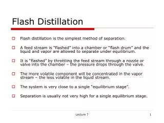
Multi-component Distillation Introduction:- As we do with binary columns, we’ll work with ideal stages which can be converted to real stages using an efficiency factor. The limiting cases of total and infinite reflux apply to multi-component columns just as they do to binary systems. The overall approach to solving multi-component problems is the same as we use for all equilibrium stage system. Use the equilibrium relationships and the operating relationships. Review multi-component bubble point and dew point calculations.
Steps for calculations:- 1- Calculate Ki values for each component ( ki = P◦i/PT) 2- Assume L / V 3- Calculate ∑yi = ∑xFi (1+L/V)/(1+L/Vki) If ∑yi ≠1 repeat your assumption of L/V If ∑yi=1 → your assumption is correct then calculate ∑ xi =1 . (solution is by trial and error)
Calculations of dew point and bubble point:- A-Bubble point:-
2-Multi-Stage Multi-component Distillation:- Key Components:- Suppose a four component mixture A-B-C-D in which A is the most volatile and D is the least volatility is to be separated as shown in the following table. Then B is the light key appearing in the bottoms and is termed light key (LK) component ꞊ xwLK And C is the heaviest component appearing in the distillate and is called the heavy key (HK) component ꞊ xDHK All other components are called the non-keys components.
Plate to plate calculations for multi-component distillation:- Calculation from plate to plate are based upon the bubble-point and dew-point calculations coupled with mass balances at each plate. There are many methods for calculation number of plates necessary for given separation and composition on each plate. From these methods: 1-Lewis-Matheson Method (equimolar flow rates). The method proposed by Lewis Matheson is essentially the application of Lewis-Sorel method to the solution of multi component problems (general method).
Constant molar overflow is assumed and the material balance and equilibrium relationship equations are solved stage by stage starting at the top or bottom of the column. In this method we must specify the following variables:- 1)Feed composition, flow rate, reflux ratio and condition (q ). 2)Distribution of key-components. 3)Products flow rates. 4)Column pressure. 5)Assumed values for the distribution of non-key components. The usual procedure is to start the calculations at the top and bottom of the column and proceed toward the feed point. The initial estimates of the component distributions in the products are then revised and the calculations repeated until the compositions calculated from the top and bottom match at the feed point.
Notes:- Lewis Matheson Method:- 1-Similar to Lewis method. 2-Tray to tray calculations are done with the assumption of constant molar flow rates of liquid and vapour in each section. 3-Top section tray to tray calculations are done till xi ≤ xFi 4-Bottom section tray to tray calculations are done till yi ≥ xFi
Top section:- L1 = L2 = L3 = --------- = L V1 = V2 = V3 = -------- = V Bottom section:- L’1 = L’2 = L’3 = --------- = L’ V’1 = V’2 = V’3 = -------- = V’ (where molal latent heats are mainly the same) • Reflux ratio = R = L/ D • V = ( L + D ) = D ( L/D + 1) = D ( R + 1 ) • From overall (M.B) on the column , calculate D ,W. • Then calculate L & D.
From feed conditions ( q )calculate L’ & V’. • q = L’ – L / F → calculate L’ . • q – 1 = V’ – V / F → calculate V ‘ . Calculation steps:- Top section:- 1- Assume total condenser conditions i.e y1i = x Di = x oi 2-Knowing key components compositions assume xDi ′s 3-Calculate x1i′s from y1i = K1i x1i ( assume T1 , calculate ki1 = P◦1i / PT then check T1 at ∑ x1i = 1 if not repeat )
4- Substitute in the overall material balance equation of the top section:-
Bottom section:- First start with the reboiler(partial vaporizer is considered as one theoretical stage)
At feed entrance we make matching between top and bottom and feed streams to check whether the assumption of xDi’s is correct or not. If not repeat your assumption, but if it match calculate the number of stages. To perform these calculations we must know the equilibrium relations (calculate K=f(T,P)) and the operating pressure . BUT operating temperature varies from tray to another, so each tray calculations will be done by assuming T and checking it from Sx or Sy (as if it’s a normal flashing problem).
2- Constant relative volatility method:- By calculating the equilibrium composition of vapor and liquid at a single plate, K-values must be known, but these cannot be determined until the stage temperature is determined which is a function of composition. Trial and error procedure is required. Much of trial and error can be eliminated if the relative volatility is used in place of K. The relative volatilities are referred to one key components(heavy key) .
Repeat your calculations till reaching feed entrance then make matching between top and bottom and feed streams to check whether the assumption of xDi’s is correct or not. If not repeat your assumption, but if it match calculate the number of stages.
3-Short-cut methods for stage and reflux requirement:- Most of the short-cut methods were developed for the design of separation columns for hydrocarbon Systems in the petroleum and petrochemical system industries. They usually depend on the assumption for severely non-ideal systems. From these methods:- 1- Pseudo-Binary system method = Hengstebeck’s method 2-Gilliland, Fenske , Underwood Method.
1-Pseudo-Binary system method = Hengstebeck’s Method:- Changes the multi-component system to binary system. Using Mc-cabe Thiele Equations:-
Gilliland, Fenske , Underwood Method:- 1- Gilliland Equation for calculation the number of stages at operating reflux:- A simple empirical method is used for preliminary Estimates. The correlation requires knowledge only of the minimum reflux ratio. This is shown in the following figure, where the group :- (N - N min)/(N + 1) is plotted against ( R – R min ) / ( R + 1 ) .
Where N = no. of plates. R = reflux ratio. N min=minimum no. of plates. R min= minimum reflux ratio.
2-Fenske equation for calculation minimum number of plates :-
Location of feed tray • Is critical to column efficiency:- • Basis for estimate:-