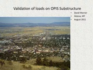
Validation of loads on OPIS Substructure
280 likes | 471 Vues
Validation of loads on OPIS Substructure. David Warner Helena, MT August 2011. Hammerhead Single column Spread footin g. Opis Substructure Peeling open the black box. Confirming Loads. I checked my coworkers pier design, then, Another coworker and I discussed testing Opis Substructure.

Validation of loads on OPIS Substructure
E N D
Presentation Transcript
Validation of loads on OPIS Substructure • David Warner • Helena, MT • August 2011
Hammerhead Single column Spread footing Opis SubstructurePeeling open the black box
Confirming Loads • I checked my coworkers pier design, then, • Another coworker and I discussed testing Opis Substructure. • Back in 6.0. • Modeling which follows is for a Spread footing, single column, hammerhead. • Blend of coworkers design and my checking techniques, then verified step by step in Substructure. • Help designers verify software • Ultimately the engineer’s responsible.
Objectives Validation of Dead, then Live loads. • By these methods. • Substructure model assumed complete. Loads confirmed only. • Confirm self weights and superstructure DL’s • Compare DL by hand with OPIS. • When comfortable with DL, add in one lane of Live load. • Show HL-93 Truck pair plus lane by hand. • Add one lane Live load and gather spread footing pressure results. Service 1 limit state, DC, DW, LL (one lane), no other loads. Compare results of OPIS and those by hand. • Familiarize • Show steps to reanalyze • Show steps to spec check • Show where to find results
Substructures Superstructure connection • Top Down. • Substructure piers start in the Bridge Alternative • Abutments aren’t analyzed directly, but… • A pier with one very short span might imitate an abutment.
Pier buttons • 3D schematic • Many views. • Generate Model • Nodes, releases • Load Combinations • Service 1, Strength • Load Pallet • DC, DW, LL, etc. • Analyze Substructure • analyze • Spec Check • Populate checks • Substructure Tabular Results • customizable • View Analysis Output • Preformed reports • Spec Check Detail • recognizable Buttons only visible with pier alternative highlighted.
Pier geometry and DL’s 3-D Schematic button (previous slide) then click isometric view, and detailed dimensioning Super Dead Loads by hand. Girders, Deck, Additional, Self Weights. table of DL’s of Superstructure then Substructure Note DL and Pressure
Weightless concrete or soil Start with few loads. Add in more loads once confident of the results.
Load Palette Turn off all but DC. Verify Add next Verify Repeat… Gain model confidence.
DL by Override Time Stamp. Dead loads from Opis Superstructure If there’s 2 or more piers, they easily copy/paste. Dead loads entered manually. Once Overrides verified; turn off. Thus using Opis loads.
Every step shown. • Generate Model, Generate model button bottom left, ok • Analyze Substructure, review any errors/warnings, continue analysis • Spec Check, continue with Spec Check (Loads same, only change is rebar?) • Review Results • Substructure Tabular Results Spec Check Detail View Analysis Output • Everything + customizable Components basic reports
DL only results Remember Pier Geometry and DL sheet? I know 97.9kPa and 6655KN are results. No moment = symmetry gain model confidence Turn off override DL, analyze again.
Dead loads DC, DW ok? • Dead loads • Correct moment • Correct axial • Additional dead loads? • Go back to add dead loads • Additional self weights • Soil • Move on to Live loads.
HL-93 Truck pair + Lanecontrols transverse moment at pier Unfactored lane Unfactored truck pair
Match design load placement transversely to OPIS’s travelway Note distance: Travelway from edge of deck: 320mm this case.
Pier geometry with girder LL reactions • Finished Groundline • Depending on your foundation type may need to find equations to help match your work to Opis Substructure results.
Effective footing width • MDT Str. Man. Fig 20.2C. Internet link below • Eccentricity (e) = Moments/Vertical loads LRFD 11.6.3.2. (following page) • Vertical loads DL = 6655KN – same as OPIS LL = 906+238 = 1144KN 90% truck pair + Lane DL + LL = 7799KN total axial. • e = 4803.5/7799 = 0.616m • With these values I’ll verify OPIS results. http://www.mdt.mt.gov/other/bridge/external/structures-manual/part_II/chp-20-final.pdf
Top two identical: equal pressure e same both cases Bottom picture and its equations are what were used for structural footing design while checking coworkers pier And Opis reports in Spec Chec Detail Loads and Reactions on spread footings the same pressure distribution See also LRFD: 10.6.1.4; 10.6.5; C5.13.3.6.1-1.
Verify model. Compare Spec Check I know all the variables shown here, now we’ll have Opis place the superstructure Live load on the pier. And compare the two a few slides. As shown on Loads and Reactions table (following) Max Pressure --------------------- And Min Pressure-----------------------
Opis’s Live Load: One Lane far side of travelway Override Live Loads Compute DL and LL Reactions will only work with all pier defined
We’ve analyzed again: Results for DL + LL My work by hand for D.L. and L.L. with resulting footing pressures. OPIS’s spread footing results table. 97.9kPa down to 65kPa due to overturning
Many ways for viewing results.Shear in the cap due to live load.3D schematic – results view
Authoring Report Styles. Glasses: Many useful preformed reports New Tabular Report.xml; Viewed in internet browser. Give a unique name, otherwise new overwrites old. Find files in install folder Spec Check Results
Specification Check Most recognizable to OPIS Superstructure users. OPIS Substructure Spec Check.
Questions and comments • Opis Substructure • Questions? • dwarner@mt.gov email any questions.