Download
1 / 26
260 likes | 278 Vues
Explore the installation, synchronization, and system overview of the Sector Collector in the CMS DT Trigger System for Muon detection and triggering at LHC. Learn about the Sector Collector boards' functions and connectivity for precise data transmission to counting room electronics. Details on the hardware features, synchronization processes, and deployment timeline are also provided.

E N D
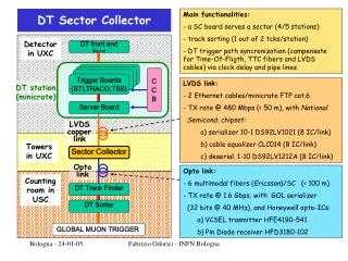
The Sector Collector of the CMS DT Trigger System: Installation and Performance R.Travaglini Physics Dept. & INFN Bologna TopicalWorkshopon ElectronicsforParticlePhysics2008 Parallel Session A6 – Trigger 2 19 Sept 08
barrel Muon detection in the barrel region of the CMS experiment at LHC “barrel” iron yoke segmented in 5 wheels Wheels arranged in 30° azimuthal sectors 4 muon stations x sector Each station equipped with DT and RPC 12 sector x wheel 250 stations 170000 cells • DT chambers perform muon detection and triggering 250 chambers (staggered layers of drift tubes) R.Travaglini Physics Dept. & INFN Bologna
DT Level-1 Trigger Systemand the Sector Collector • CMS Muon Trigger • Muon identification • Transverse momentum (Pt ) measurement • Assignment to the correct Bunch Crossing • Drift Tubes Level 1 Trigger (custom electronics) • On-detector : local ( = any chamber) muon identification and selection of 2 track segments with higher Pt • Reliability • Radiation tolerance (ASICs, pASICs) • Off-detector : correlates chamber information (track finding) • The Sector Collector boards have to: • Collect local output from 4 chamber electronics each one • Synchronize them • Transmit data (properly remapped) to the counting room electronics R.Travaglini Physics Dept. & INFN Bologna
Sector Collector system:location and data transmission Regional trigger electronics (underground counting room) SC Output links : 6 optical @ 1.6 Gbit/s per link 1 GOL chip per link SC Input links : Cat-5 FTP cables (480 Mb/s LVDS) : 2 copper cables/chamber 4 twisted pairs/cable Located on detector towers, 60 SC boards (1/DT 30° sector), 2 VME 9U crates / wheel R.Travaglini Physics Dept. & INFN Bologna
Sector Collector system overview Tower crates Underground Counting room Opto TX (60) Opto RX (60φ+24η) LVDS RX [ 240 2ch + 10 4ch) ] SC Motherboard (60) R.Travaglini Physics Dept. & INFN Bologna
Sector Collector crate LVDS copper cables R.Travaglini Physics Dept. & INFN Bologna
Sector Collector implementationmain hardware features • Processing devices used on Near-detector electronics: ProAsicPlus 300, FPGA from Actel(456 balls) • configuration memory is FLASH-based (rad-hard) • on board programming via custom VME-Altera Jtag interface Independent Mezzanine powering: each mezzanine (LVDS-Rx and Opto-Tx) can be Powered off in case of failure with I/O lines isolation Spying: a partial copy of the trigger data (quality bits, ...) from any chamber is injected in the DAQ-boards located in the same VME crate Control:I2C bus accessing temperature and current sensors; JTAG chain for meazzinines FPGA access (boundary scan, configuration, ...) • Counting room:Altera StratixGX FPGA (672 balls) • with 8 embedded gigabit transceivers R.Travaglini Physics Dept. & INFN Bologna
DT trigger synchronization with the Sector Collector (1):desynchronization sources 2 lvds copper cables per chamber 10 m < L < 40 m 30° sector of the DT detector Every chamber electronics act as a synchronous system, only its overall clock phase vary, depending on its relative tuning w.r.t. LHC beam phase => Different chambers have different phases Skew between Max lenght link and Min lenght link < 20 ns Looking at fibers for all wheels 6 optical links per sector R.Travaglini Physics Dept. & INFN Bologna
parity error flag parity error flag DT trigger synchronization with the Sector Collector (2):synchronization tools Fine Synchronization (sector synch) parity check Cable up (4 LVDS ch) CK Cable dw (4 LVDS ch) parity check CK 30° sector of the DT detector Each mezzanine has independent delayble sampling clock (32 step – 1ns/step) Coarse Synchronization (cross-sectors synch -> wheels synch) chambers Sector Collector Coarse synch performed by looking at: Orbit signal (BC0) as well as spied data R.Travaglini Physics Dept. & INFN Bologna
Sector Synchronization Coarse synchronization of stations (one station triggers spy regs; look for trigger coincidences in others) cable Sampling Ck delay (1ns/step) Fine synchronization of Input links (parity bit check) R.Travaglini Physics Dept. & INFN Bologna
Installation, commissioning and integration tests • Devices production (Jan 07 to Mar 07) , tests and installation on situ (ended in Jul 07) have been relatively fast • Commissioning step 1: • Electronics commissioning performed together with commissioning of DT detector and electronics in whole sectors (4 chambers ,local electronics, read-out and control chains, ...) • Commissioning step 2: • Wheel by wheel commissioning • A dedicated technical trigger for cosmics muon based on DT trigger electronics have been implemented for commissioning • Since June 07 DT system is partecipating to CMS integration tests • (Global Runs) aimed to integrate subdetectors in common data-taking • Starting from few sectors partecipating in Jun 07 in the last Global Run (August 08) the whole DT subsystem was included • DT trigger has been included from the beginning, providing a reliable trigger on cosmics muons, suitable for data-taking, syncronization issues and performance studies R.Travaglini Physics Dept. & INFN Bologna
DT Trigger at Global Runsevent display examples Timing With ECAL Trigger of track crossing adjacent sectors Cosmic trigger on opposite sectors for Tracker R.Travaglini Physics Dept. & INFN Bologna
Example of Muon Trigger performances:track reconstruction Z (cm) Z (cm) CMS preliminary CMS preliminary X (cm) X (cm) Tracks extrapolated to the (earth) surface in CMS coordinates: most of muons from the pit Average probability of a track to pass trough the bottom of CMS if detected at top projection to the earth surface: shaft muons are softer Courtesy of I.Mikulec R.Travaglini Physics Dept. & INFN Bologna
DT muon technical trigger Standard DT trigger path MINICRATES SC Track Finder Wedge Sorter Barrel Sorter Global Trigger Global Muon Trigger optolink Technical Trigger Bits CAEN V976 L1 accept (V976) SC Track Finder • Each Trak-finder device delivers a Technical Trigger Bit if at least one chamber of the correnspondant sector has triggered • Cabled logic is implemented with CAEN V796 (Quadf 4 Fold AND/OR/MAJ, NIM-TTL TTL-NIM Translator, Fan-In Fan-Out ) modules • Still not integrated with the CMS Global Trigger as a Official Technical Trigger (soon!); used in commissioning and DT-local data-taking R.Travaglini Physics Dept. & INFN Bologna
Examples of using the DT muon technical trigger • DT Technical Trigger useful for studies at very low luminosity LHC beam: • For instance, requiring a global OR of all DT chamber: • Trigger rate due to cosmics muon: • Rate < 300 Hz • Trigger rate due to collision events: • Rate (L = 1031) < 500 Hz A useful sample of data needed for DT trigger synchronization can be taken in few hours ! R.Travaglini Physics Dept. & INFN Bologna
Sector Collector control software • Tasks: • Retrieving HW configuration from DB • Automatic power on of all mezzanines • Hw configuration • Monitoring of error flags, temperatures, current drawings, ... • Exporting of monitored data to DB • User-friendly panels showing the sistem health All crates in parallel Example of performance when configuring the whole system: cold start (all mezzanines off) : < 30 s warm start (only HW config) : 1 s R.Travaglini Physics Dept. & INFN Bologna
A CMS common framework for L1 Trigger control: Trigger Supervisor The Trigger Supervisor is a common framework designed for set up,operate and monitor the CMS L1 trigger devices and the information exchange with the run control and the global CMS monitoring system (http://triggersupervisor.cern.ch) It provides facilities for customizing single applications (called “cells”), their communications (via SOAP messages), connections with databases (for storage of hardware configurations and run conditions) and graphical user interfaces for managing cells via http client R.Travaglini Physics Dept. & INFN Bologna
Overview of the Trigger Supervisor implementation for the Sector Collector SOAP messages Main cell http SOAP messages shifter http ... X 5 wheels 1 supervisor 10 workers (2 per PC) expert user R.Travaglini Physics Dept. & INFN Bologna
Screenshots (1) crates sectors R.Travaglini Physics Dept. & INFN Bologna
Screenshots (2) One panel per crate One graph per board (8 sensors per board) R.Travaglini Physics Dept. & INFN Bologna
Summary • The Sector Collector system, for the CMS L1 trigger, has been presented • It consists of: • 60 9U VME boards equipped with LVDSreceiver mezzanines, • optical transmitter (@ 1.6 Gbit/s) and • optical receiver cards (placed in counting room) • Several tools have been foreseen on the Sector Collector in order to achieve proper • synchronization of the DT trigger devices (both sector and wheel level) as well as • with the whole detector • The Sector Collector system has been successfully commissioned and provided • stable and realiable triggering on cosmicmuons during CMS Global Runs • A control software application have been developed and integrated with the CMS • Level 1 Trigger framework R.Travaglini Physics Dept. & INFN Bologna
Additional slides R.Travaglini Physics Dept. & INFN Bologna
CMS Level-1 Trigger System • LV1 trigger: • processes events @ 40 MHz (no dead time) • based on pipeline processing • selects events reducing accepted rate • up to 100 kHz • relies on custom electronics • low latency (3.2 μs) decision R.Travaglini Physics Dept. & INFN Bologna
DT Local Trigger • Synchronous pipelined system (40 MHz) • Processing stages organized in a logical tree structure 40000 ASICs 4400 ASICs Arranged into a Mini-Crate located on the detector (w. Read-out elctr.) 1200 ASICs + 250 x3 pASIC R.Travaglini Physics Dept. & INFN Bologna
Production and test strategy R.Travaglini Physics Dept. & INFN Bologna
Test setup 6U VME crate (VME bridge, Pattern Units (high speed I/O devices), clock fanout...) LVDS-TX connected to a Pattern Unit (data injection, emulates the minicrate) Custom J3 (TTC signals) Opto-rx connected to a Pattern Unit for pattern acquisition (emulates the DTTF) SC under test TIM (TTC signals fanout) R.Travaglini Physics Dept. & INFN Bologna