Download
1 / 98
980 likes | 1.16k Vues
UPV-UV Valencia iGEM 2006. Alfonso Jaramillo Ecole Polytechnique, Paris & InterTech (UPV). Summary of work plan. April: Training lectures, promotion, team building and funding. May/June: Prototype design. July/August: Parts & Devices construction & characterization. Redesign prototype.

E N D
UPV-UV Valencia iGEM 2006 Alfonso Jaramillo Ecole Polytechnique, Paris & InterTech (UPV)
Summary of work plan • April: Training lectures, promotion, team building and funding. • May/June: Prototype design. • July/August: Parts & Devices construction & characterization. Redesign prototype. • September/October: System characterization.
Outline • Biological modules for engineering • Parts • Devices • Systems • Design of parts
Biological modules for engineering • Chassis: Bacterial strain that will receive the engineered systems. • Parts: Fragment of DNA with a given functionality. • Devices: Assembly of parts with a given functionality and given interface. • Specifications • I/O is given by proteins and signals • Systems: Assembly of devices with a given functionality • I/O is given only by signals
Systems PoPS NOT.1 PoPS NOT.2 PoPS NOT.3 ‘Can I have three inverters?’ ‘Here’s a set of PDP inverters, 1N, that each send and receive via a fungible signal carrier, PoPS.’ PoPS NOT.1 Devices PoPS PoPS ‘I need a few DNA binding proteins.’ ‘Here’s a set of DNA binding proteins, 1N, that each recognize a unique cognate DNA site, choose any.’ Parts ‘Get me this DNA.’ DNA ‘Here’s your DNA.’ TAATACGACTCACTATAGGGAGA Zif268, Paveltich & Pabo c. 1991
Biological Engineering • Decoupling • Rules insulating design process from details of fabrication • Enable parts, device, and system designers to work together • VLSI electronics, 1970s • Standardization • Predictable performance • Off-the-shelf • ME, 1800s • Abstraction • Insulate relevant characteristics from overwhelming detail • Simple artifacts that can be used in combination • From Physics to EE, 1800s
Parts • Promoter • RBS • CDS • Terminator • Tag • Primer • Operator Notice that for the MIT registry, any combination of parts (e.g. devices and systems) is a part. = BBa_M30109
Parts Construction • Simplified cloning procedure that allows to combine plasmids using a standardized approach. • The construction of devices is reduced to the combination of parts (to generate new parts, in the MIT terminology). • Careful with the maximum size of plasmids
Parts Construction E X S P
Standard PCR and sequencing primers have been chosen for pSB103 to use for colony PCR for insert length selection, and for sequencing of inserts: Verication Forward: 5' TTG TCT CAT GAG CGG ATA CA 3‘ Verication Reverse: 5' ATT ACC GCC TTT GAG TGA GC 3’.
cut the green plasmid with EcoRI and XbaI enzymes. cut the blue plasmid with EcoRI and SpeI, A minimum number of bases (undetermined) between the EcoRI and XbaI sites and the SpeI and PstI sites may be required to allow complete cutting with both enzymes (NotI).
The vector and insert must not contain any other EcoRI, XbaI, SpeI, or PstI cut sites. This excludes • the following hexamer sequences: • EcoRI: GAATTC • XbaI: TCTAGA • SpeI: ACTAGT • PstI: CTGCAG And octameric recognition site for NotI, GCGGCCGC.
Devices • They should be able to always produce the same ouput from the same input. • Need of specification of transfer functions and I/O proteins/molecules. • The engineer will be able to model the devices from the specifications without needing to know the internals. Encapsulation of data. • Devices with interface with each other. Need of a standard. • In the real world the devices will interact with the chassis.
Devices LacI CI inverter LacI CI
CI LacI Devices CI LacI RBS l cI-857 OLac T
Systems Inverter.1 Inverter.2 Inverter.3
cI LacI cI PoPSin RBS l cI-857 OLac T RBS l cI-857 Ol T PoPSout cI PoPSout PoPSin LacI Device Interface
PoPSOUT PoPSIN cI T RBS l cI Ol Polymerase Per Second = PoPS! T RBS l cI Ol
PoPSOUT PoPSOUT PoPSIN PoPS Source (Any) INVERTER PoPSOUT PoPSIN Polymerase Per Second = PoPS! PoPSOUT PoPSIN T RBS l cI Ol cI
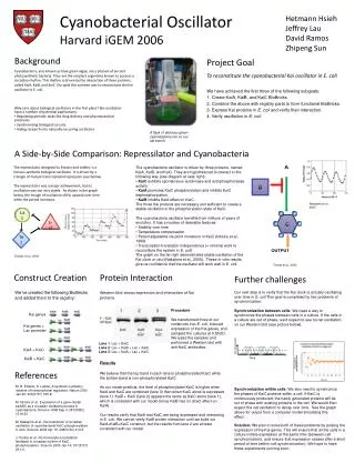
Towards an Ideal Chassis • We would like to have a chassis that will not interfere with our devices. • We need a dedicated protein production.
Biological Virtual Machines • Dedicated systems are a method to decouple the function of an engineered biological system from the function of its chassis. • By separating the resources and machinery used to supply and power an engineered system from those of the chassis, then perturbations in the operation of one should have less effect on the other. • These dedicated synthesis systems can then be used as the basis of Biological virtual machines.
The T7 expression system developed by Studier and coworkers is essentially orthogonal from the E. coli transcription system. T7 RNAP does not recognize E. coli promoters and E. coli RNAP does not recognize T7 promoters.
Gene Design http://slam.bs.jhmi.edu/gd/
natural linker peptides between F1 and F2 (TGQKP) and between F2 and F3 (TGEKP), bind DNA containing the 18-nt site 5'-GCGTGGGCGGCGTGGGCG-3'. Barbas PNAS 97 Designed linker sequence TGEKP between E3 and F4.
Factors that Influence Gene Expression • Codon Usage: there is little tRNA made for rare codons. In E. coli these are mainly AGA and AGG (Arg codons). The genes encoding the tRNAs can be co-overexpressed. • Promoters used should be very tight. Tight promoters are for example arabinose (BAD), rhamnose and lactose (provided that lacIQ is co-overexpressed). • RBS (Shine-Delgarno Sequence - serves to align the ribosome on the message in the proper reading frame.) Optimal: AGG AGG, the last G should be 9 bases upstream from the A of the AUG (start of translation) Start codons on mRNA are: AUG (90%, codon for Met), GUG (9%), UUG (1%) and CUG (0.1%). Avoid secondary structure involving SD sequence and the initiator AUG. In polycistronic mRNAs, the initiation site should be close to the termination codon of the upstream gene. • Regulation of translation: is sometimes (not often) affected by sequences in the coding region: +5 and +10 should be A or T • RNA Stability can be increased if stem-loop structures are cloned at the 3' end of the coding region
Expression Vectors • Low copy number plamids are better than high copy number plasmids (copy numbers of 5-40 is recommended). • Yield of protein does not linearly correlate with copy number of a gene. • Regulated promoter - the optimum is one that is induced by a substrate such as IPTG that diffuses into the cell because then induction levels can be more easily manipulated. • Inducers that are a substrate of one or more active transport systems cannot be controlled at all. These inducers will be accumulated to mM levels even when added in very low concentrations to the growth medium. • Co-overexpression of repressors of the promoter used can provide excellent control of transcription. Co-overexpression of activators guarantees that each promoter on the plasmids is activated. • Place transcription terminator at the 3' end of target gene. This avoids formation of antisense RNAs from downstream promoters operating in reverse orientation with respect to the gene that should be expressed at high levels.
Getting folded proteins • Broken protein domains don't fold • Difficult to get folded in the cytoplasm a protein containing disulfide bonds. • Coexpress other members of a hetero-oligomeric complex • Inclusion body formation can often be reduced by growing cells at 200C (Note that 280C does not work nearly as well). If this is not successful, try adding 6% ethanol to rich medium when adding inducer. EtOH induces heat shock response which overexpresses chaperones and proteases. The latter are barely active at 200C.
Parameters E.Coli parameters: http://redpoll.pharmacy.ualberta.ca/CCDB/cgi-bin/STAT_NEW.cgi DNA and RNA molecular weights: http://www.ambion.com/techlib/append/na_mw_tables.html
Design of Devices Example of devices: Regulatory, input, output, sensors, signaling, metabolic, etc…
Modeling a Biochemical Inverter input repressor promoter output
Steady-State Behavior: Transfer Functions Inverter “ideal” transfer curve: • gain (flat,steep,flat) • adequate noise margins “gain” [output] 0 1 [input] This curve can be achieved using proteins that cooperatively bind dna!
“drive” gene Measuring a Transfer Curve • Construct a circuit that allows: • Control and observation of input protein levels • Simultaneous observation of resulting output levels inverter CFP YFP R output gene • Also, need to normalize CFP vs YFP
plasmid IPTG (or ECFP) Drive Input Levels by Varying Inducer IPTG (uM) lacI [high] YFP 0 (Off) P(R) P(LtetO-1) IPTG 0 250 1000 promoter protein coding sequence
Controlling Input Levels Also use for yfp/cfp calibration
aTc tetR [high] lacI CFP 0 (Off) YFP P(R) P(lac) P(LtetO-1) aTc measure TC Measuring a Transfer Curve for lacI/p(lac) “drive” output
Transfer Curve Data Points 01 10 undefined 1 ng/ml aTc 10 ng/ml aTc 100 ng/ml aTc
tetR [high] lacI CFP 0 (Off) YFP P(R) P(lac) P(LtetO-1) aTc lacI/p(lac) Transfer Curve gain = 4.72
Noise margins: Evaluating the Transfer Curve • Gain / Signal restoration (95%): high gain FACS cell population data • note: graphing vs. aTc (i.e. transfer curve of 2 gates)