
Data Link Layer Sublayers: LLC and MAC Functions
E N D
Presentation Transcript
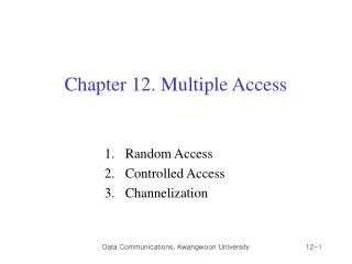
Chapter 12 Multiple Access
Figure 12.1 Data link layer divided into two functionality-oriented sublayers • Upper sublayer – responsible for data link control • Called LLC – for flow and error control • Lower sublayer - responsible for resolving access thesharedmedia • Called MAC – for multiple acceess resolution
Figure 12.2 Taxonomy of multiple-access protocols discussed in this chapter
12-1 RANDOM ACCESS In random access or contention methods, no station is superior to another station and none is assigned the control over another. No station permits, or does not permit, another station to send. At each instance, a station that has data to send uses a procedure defined by the protocol to make a decision on whether or not to send. The decision depends on the state of the medium (idle or busy). Topics discussed in this section: ALOHACarrier Sense Multiple Access Carrier Sense Multiple Access with Collision Detection Carrier Sense Multiple Access with Collision Avoidance
Figure 12.3 Frames in a pure ALOHA network Pure ALOHA: 1. Each station sends a frame whenever is has a frame to send 2. One channel to share, possibility of collision between frames from different stations
Figure 12.6 Frames in a slotted ALOHA network Slotted ALOHA: 1. We divide the time into slots and force the station to send only at the beginning of the time slot
Figure 12.8 Space/time model of the collision in CSMA CSMA – each station first listen to the medium before sending Principle : “sense before transmit” or “listen before talk”
Figure 12.10 Behavior of three persistence methods 1-Persistent-after station finds the line idle, send its frame Nonpersistent-senses the line; idle: sends immediately; not idle: waits random amount of time and senses again p-Persistent-the channel has time slots with duration equal to or greater than max propagation time
Figure 12.12 Collision of the first bit in CSMA/CD Figure 12.13 Collision and abortion in CSMA/CD CSMA/CD- Augments CSMA algorithm to handle collision
Example 12.5 (Minimum frame size) A network using CSMA/CD has a bandwidth of 10 Mbps. If the maximum propagation time (including the delays in the devices and ignoring the time needed to send a jamming signal, as we see later) is 25.6 μs, what is the minimum size of the frame? Solution The frame transmission time is Tfr = 2 × Tp = 51.2 μs. This means, in the worst case, a station needs to transmit for a period of 51.2 μs to detect the collision. The minimum size of the frame is 10 Mbps × 51.2 μs = 512 bits or 64 bytes. This is actually the minimum size of the frame for Standard Ethernet.
Figure 12.15 Energy level during transmission, idleness, or collision Zero level–channel is idle Normal level–successfully captured channel and sending frame Abnormal level-collision and energy twice the normal level
Figure 12.16 Timing in CSMA/CA Avoid collisions on wireless network because they cannot be detected IFS- In CSMA/CA, the IFS can also be used to define the priority of a station or a frame. Contention window- In CSMA/CA, if the station finds the channel busy, it does not restart the timer of the contention window; it stops the timer and restarts it when the channel becomes idle. Acknowledgment- Positive acknowledgment and time out timer guarantee receiver has received the frame
12-2 CONTROLLED ACCESS In controlled access, the stations consult one another to find which station has the right to send. A station cannot send unless it has been authorized by other stations. We discuss three popular controlled-access methods. Topics discussed in this section: ReservationPollingToken Passing
Figure 12.18 Reservation access method Reservation-station needs to make a reservation before sending data
Figure 12.19 Select and poll functions in polling access method Polling – one device as primary station and the other device as secondary station Select – primary device wants to send data to secondary device, secondary device gets ready to receive Poll – primary device solicits (ask) transmissions from secondary devices
Token passing – stations in network organized in a logical ring – predecessor and successor Token – gives station right to access the channel; needs token management Physical ring – station sends the token to successor Dual ring – uses second ring which operates in reverse direction Bus ring (token bus) - stations are connected to single cable called bus, but make logical ring Star ring - physical topology star, wiring inside hub makes the ring
Figure 12.20 Logical ring and physical topology in token-passing access method