Download
1 / 26
270 likes | 461 Vues
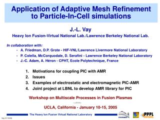
Application of Adaptive Mesh Refinement to Particle-In-Cell simulations. J.-L. Vay Heavy Ion Fusion-Virtual National Lab./Lawrence Berkeley National Lab. In collaboration with: A. Friedman, D.P. Grote - HIF-VNL/ Lawrence Livermore National Laboratory

E N D
Application of Adaptive Mesh Refinement to Particle-In-Cell simulations J.-L. Vay Heavy Ion Fusion-Virtual National Lab./Lawrence Berkeley National Lab. In collaboration with: • A. Friedman, D.P. Grote - HIF-VNL/Lawrence Livermore National Laboratory • P. Colella, McCorquodale, D. Serafini - Lawrence Berkeley National Laboratory • J.-C. Adam, A. Héron - CPHT, Ecole Polytechnique, France • Motivations for coupling PIC with AMR • Issues • Examples of electrostatic and electromagnetic PIC-AMR • Joint project at LBNL to develop AMR library for PIC Workshop on Multiscale Processes in Fusion Plasmas UCLA, California - January 10-15, 2005
Goal: end-to-end modeling of a Heavy Ion Fusion driver challenging because length scales span a wide range: mm to km(s)
In driver -12 -11 -10 -9 -8 -7 -6 -5 -4 -3 -2 -1 0 In chamber Time and length scales in driver and chamber span a wide range Time scales: depressed betatron betatron t electron drift pb out of magnet » transit lattice thru electron period fringe beam cyclotron pulse fields residence in magnet log of timescale pulse beam t pe in seconds residence t pi t pb Length scales: • electron gyroradius in magnet ~10 mm • lD,beam ~ 1 mm • beam radius ~ cm • machine length ~ km's
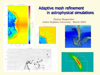
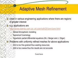
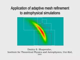
3D AMR simulation of an explosion (microseconds after ignition) AMR concentrates the resolution around the edge which contains the most interesting scientific features. The Adaptive-Mesh-Refinement (AMR) method • addresses the issue of wide range of space scales • well established method in fluid calculations • goal: develop successful PIC-AMR
Mesh Refinement in Particle-In-Cell: Issues • Asymmetry of grid implies asymmetry of field solution for one particle • spurious self-force • Some implementations may violate Gauss’ Law • total charge may not be conserved exactly • EM: shortest wavelength resolved on fine grid not resolved on coarse grid may reflect at interface • if reflection factor <=1, spurious waves • if reflection factor >1, may cause instability by multiple reflections Remark: BTW, these are general and apply also to PIC on irregular grids!
“Mother” grid Patch grid Electrostatic: possible implementations • Given a hierarchy of grids, there exists several ways to solve Poisson. • Two considered here: • ‘1-pass’ • solve on coarse grid • interpolate solution on fine grid boundary • solve on fine grid • different values on collocated nodes • ‘back-and-forth’ • interleave coarse and fine grid relaxations • collocated nodes values reconciliation • same values on collocated nodes
Metallic boundary “Mother” grid Patch grid zoom Test particle Spurious “image” particle trapped in patch one particle attracted by its image as if there was a spurious image Illustration of the spurious self-force effect • 1 grid with metallic boundary + 1 refinement patch • MR introduces spurious force,
1-pass multipass Log(E) Linear y Quadratic x Self-force amplitude map and mitigation main grid patch transition region • Magnitude of self force decreases rapidly with distance from edge • with the 1-pass method, the self-force effect can be mitigated by defining a transition region surrounding the patch in which deposit charge and solve but get field from underlying coarse patch
Electromagnetics: usual scheme Rf P Rc: coarse resolution Rf: fine resolution Rc G • the solution is computed as usual in the main grid and in the patch • interpolation is performed at the interface • unfortunately, most schemes relying on interpolations have instability issues at short wavelengths (the ones that may be generated in the patch but cannot propagate in the main grid)
Illustration of instability in 1-D EM tests o: E, x:B * Most schemes relying on interpolations are potentially unstable. Space only Space+Time * J.-L. Vay, JCP (2001)
( m ) Z 3D WARP simulation of High-Current Experiment (HCX) Modeling of source is critical since it determines initial shape of beam WARP simulations show that a fairly high resolution is needed to reach convergence 1 . 0 Low res. Medium res. High res. Very High res. mm.mrad) 0 . 8 0 . 6 p ( 0 . 4 NRMS e 4 0 . 2 0 . 0 0 . 1 0 . 2 0 . 3 0 . 4
R (m) zoom Z (m) Z (m) Z (m) Refinement of gradients: emitting area, beam edge and front. Example of AMR calculation with WARPrz: speedup ~10.5 R (m) 1 . 0 Low res. Medium res. High res. Low res. + AMR 0 . 8 mm.mrad) 0 . 6 p ( 0 . 4 NRMS e 4 0 . 2 0 . 0 0 . 1 0 . 2 0 . 3 0 . 4 Z ( m )
3D WARP simulation of HCX shows beam head scrapping Rise-time t = 800 ns beam head particle loss < 0.1% x (m) z (m) Rise-time t = 400 ns zero beam head particle loss x (m) • Simulations show head cleaner with shorter rise-time • Question: what is the optimal rise-time? z (m)
di L a m p e l - T i e f e n b a c k virtual surface 1 . 0 V/Vmax current 0 . 0 t / time t 0 . 0 1 . 0 Vi irregular patch in di irregular patch in di + AMR following front “L-T” waveform N = 160 Dt = 1ns d = 0.4m Ns = 200 AMR ratio = 16 I (A) dx0/Dx~10-5! Time (s) Time (s) Time (s) 1D time-dependent modeling of ion diode Emitter Collector d V V=0 Insufficient resolution of beam front => AMR patch Careful analysis shows that di too large by >104 => irregular patch
MR patch Current history (Z=0.62m) Current history (Z=0.62m) MR off MR on MR patch key in simulation of STS500 Experiment • Mesh Refinement essential to recover experimental results • Ratio of smaller mesh to main grid mesh ~ 1/1000 * J.-L. Vay et al, PoP (2003)
Patch 2s=28/k0 fine F Extended PML core C Laser beam Outside patch: F = FM coarse Inside patch: F = FM-FC+FF coarse M Mesh refinement by substitution* 10nc, 10keV l=1mm, 1020W.cm-2 (Posc/mec~8,83) Applied to Laser-plasma interaction in the context of fast ignition New MR method implemented in EM PIC code Emi2d * J.-L. Vay, J.-C. Adam, A. Heron, CPC (2004)
same results except for: • small residual incident laser at exit of patch when patch englobes target • dip in density on patch border when patch inside target Comparison patch on/off MR off MR on MR on
Possible paths for better scheme • Use less dispersive Maxwell solver • Inject inject residual of waves on main grid at patch interface • Do not use coarse patch and solve on fine patch with source term dJ as a correction to J • Go back to usual scheme with a hole in the main grid • put PML inside hole and on fine patch border • couple using clean cross-injections PML fine F Inside patch: dJ Outside patch: J coarse M
Effort to develop AMR library for PIC at LBNL • Researchers from AFRD (PIC) and ANAG (AMR-Phil Colella’s group) collaborate to provide a library of tools that will give AMR capability to existing PIC codes (on serial and parallel computers) • The base is the existing ANAG’s AMR library Chombo • The way it works • WARP is test PIC code but library will be usable by any PIC code
Example of WARP-Chombo injector field calculation * P. McCorquodale, P. Colella, D.P. Grote, J.-L. Vay, JCP (2004)
Conclusion • AMR can be of great help for PIC multiscale plasma simulations • but scheme must be derived with care • spurious self-force • conservation of charge • reflection of waves • non-cancellations due to numerical errors (dispersion) • … • in electrostatic, ‘problem solved’ • in electromagnetic, existing schemes can be successfully applied to some problems but more research is needed to get better scheme(s) • AMR on regular cartesian grids is not the solution to everything: sometimes need to apply irregularly gridded patch which maps to some conductor, field line, …