Download
1 / 20
210 likes | 362 Vues
Explore the intricate world of CPU chips and pinouts, grasp the significance of bus architecture, and delve into efficient I/O handling techniques in computer systems.

E N D
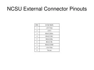
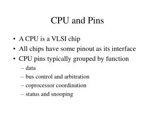
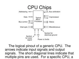
CPU Chips and Pinouts • A CPU is a VLSI chip • All chips have some pinout as its interface • CPU pins typically grouped by function • data • bus control and arbitration • coprocessor coordination • status and snooping
The Bus • It’s just a bunch of wires • Perhaps the second most important component in the whole system • Motherboards not just built around CPU • CPUs come with “buddies” called chipsets
Bus Trends • Typically multiple buses in one system • Trend is to create appropriate layers • Each layer coordinates components with similar speed • Then next problem is how to coordinate multiple components
Bus Arbitration • Sometimes CPU chip contains arbitration • Other times a separate chip handles this • Hence the idea of a chipset • Bus only allows one signaler at a time • Key arbitration mechanism is priority list • Highest priority component always wins • Smarter buses will prevent starvation
Handling Input/Output • I/O is just another bus in the system, but… • Other issues are also important for I/O • data transfers • CPU interaction with I/O component • Three ways to address these other issues • programmed I/O • interrupt-driven I/O • direct memory access (DMA) [p. 103, 385]
Programmed I/O Example • “Programmed” implies software-driven • Step 1: CPU issues request for read operation • Step 2 • device begin read operation • CPU begins polling device to see if finished • Steps 3 through n • device works on and completes read operation • CPU periodically checks device status register • Steps n+1 through n+m: CPU copies data to RAM
Interrupt-Driven I/O Example • Interrupt “informs” CPU of I/O completion • CPU has interrupt status register • checks status register at end of each instruction cycle • better than running an instruction to check status • Step 1: CPU issues request for read operation • Step 2: CPU changes tasks; I/O device begins read • Steps 3 through n: device does read operation • Steps n+1 through n+m: CPU copies data to RAM
Interrupt Masks • Chooses which interrupts can be serviced • Mask changes based on current situation • Mask typically enforced as AND gates to enable/disable interrupt signal
DMA Example • I/O device writes directly to RAM • CPU doesn’t have to do copy to RAM • Step 1: CPU issues request for read operation • Step 2: CPU changes tasks; I/O device begins read • Steps 3 through n: device does read operation • Steps n+1 through n+m: DMA copies data to RAM
Memory-mapped I/O • Done using chip select signal of I/O controller • I/O chips are typically grouped together • Individual chip chosen via chip select signal • Memory-mapped I/O controllers are different • Grouped with memory chips • CPU treats it like a memory chip • A memory address may not correspond to RAM • Address points to information on an I/O device