Electro-Oculography (EOG) Measurement System
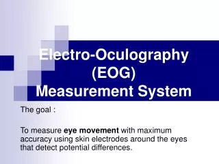
Electro-Oculography (EOG) Measurement System. The goal : To measure eye movement with maximum accuracy using s kin electrodes around the eye s that detect potential differences. Fixations ( קיבעון ): The eye is almost motionless, for example, while reading a single, short word.

Electro-Oculography (EOG) Measurement System
E N D
Presentation Transcript
Electro-Oculography (EOG)Measurement System The goal : To measure eye movement with maximum accuracy using skin electrodes around the eyes that detect potential differences.
Fixations (קיבעון): • The eye is almost motionless, for example, while reading a single, short word. • Duration varies from 100-1000 ms, typically between 200-600 ms. • Fixations are interspersed with saccades.. Types of Eye Movement (1) Saccades: • Quick “jumps” that connect fixations • Duration is typically between 30 and 120 ms • Very fast (up to 700 degrees/second) • Saccades are ballistic, i.e., the target of a saccade cannot be changed during the movement. • Saccades are used to move the fovea to the next object/region of interest.
Torsional (פיתול) Eye Movements: Rotation of the eye around the viewing axis Stabilization of visual scene by compensating body rotation (up to about 15 degrees) Types of Eye Movement (2) Smooth Pursuit Eye Movements: • Smooth movement of the eyes for visually tracking a moving object • Cannot be performed in static scenes (fixation/saccade behavior instead)
I don’t see the Zebra here, do you? Types of Eye Movement (3) Tremor (רעידה): • Fast, low-amplitude (seconds of arc) eye-movement “jitter” • Improves the perception of high spatial frequencies Vergence (פזילה) Eye Movements: • changing the vergence angle (the angle between the two viewing axes) by slow, smooth movement of the two eyes in opposite directions. • Used for changing gaze from a near to a far object or vice versa • Can take up to one second In this project we try to measure only Saccades movements using EOG !
EOG The electrical potentials around the eyes arise due to the permanent potential difference of between 10 and 30mV that exists between the cornea and the ocular fundus. This is commonly referred to as the cornea-retinal potential with the cornea being positive.
? EOG - How it works Human eye (top view) Left Right ~+100 uV ~ -100 uV Voltmeter
Placing the electrodes (1) • Horizontal eye movements can be best measured by placing the electrodes on the left and right external canthi (the bone on the side of the eye). • Vertical movements of the eyes are measured by placing the electrodes approximately one centimetre vertically above and below the eye
Placing the electrodes (2) • Acombination of the following is also possible in order to measure horizontal and vertical movements simultaneously. • By looking at the difference of Signal #1 and Signal #2and the difference of Signal #3 and Signal #4,a separation of horizontal and vertical eye movements can be made. • A reference electrode is positioned on the subject’s forehead 4 1 2 3
Horizontal vs. Vertical • The red graph on the top shows Signal #1 – Signal #2 and therefore it reflects • only horizontal eye movements (Right – Left) • The blue graph on the bottom shows Signal #3 – Signal #4 and therefore it reflects • only vertical eye movements (Up – Down)
Our Equipment (1) • In this project we had the PC-ECG device for acquiring EOG signals. • PC-ECG does the following : • Amplification of the EOG signal • 12 bit / 2kHz sampling • And some more …
Our Equipment (2) • The PC-ECG system has a pole in the origin • In such system
We need to measure DC signals and PC-ECG is completely inappropriate for this task. The Problem • The PC-ECG device can not transmit DC signals. • EOGsignal is a partially constant function
Software Inverse System (1) • The idea : If we can characterize the PC-ECG system, in other words find it’s impulse response - , the we can implement in software the inverse system and cancel the unwanted affect (cancel the zero in the origin).
Software Inverse System (2) • PC-ECG characterization : • Making recordings from eyes/signal generator we got : • Basically now we know the step response of the PC-ECG system. • Consequently the impulse response that describes the system is . • Therefore :
Software Inverse System (3) • Finding the Inverse System : After converting to discrete time by using the rectangle approximation, we get:
Software Inverse System (4) • The Results :
Software Inverse System (5) • The good news : • The Software Inverse System was able to bring the signal back to its original "Square Sine" form, which was produced by the Signal Generator. • The bad news : • Although by using the Software Inverse System we are able to correct the signal to its original form, the entire system is unstable!
Horizontal Eye Tracker (HET) • The software that we have developed does in Real Time the following things: • Data acquisition from the PC-ECG device :12 [bit], 2000 [Samples/sec] • LPF filteringof the raw signal, with cutoff frequency of approximately 30Hz • Applying the inverse system on the filtered signal. • Makes auto calibration and periodic centralization of corrected signal in order to overcome the instability problem. • Marks in red the appropriate button (Left, Center or Right) according to the corrected signal level.
Drift upwards Periodic centralization (1) • Problem 1:
Periodic centralization (2) • Solution 1:
Non zero Drift downwards Periodic centralization (3) • Problem 2:
Zero Periodic centralization (4) • Solution 2:
This is how it works Digital Signal, 12bits / 2 [kHz] Analog Signal, Amplitude ~ 100 [uV] The subject gets a feedback by seeing that the button that he is looking at becomes red.