Download
1 / 53
540 likes | 772 Vues
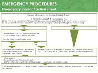
The Cirrus SR-22 transition training emphasizes critical emergency and abnormal procedures essential for pilot safety. This includes maintaining aircraft control, analyzing situations, and taking appropriate actions under various conditions. Pilots learn to distinguish between abnormal and emergency conditions, effectively execute checklists, and utilize memory items in time-critical scenarios. Procedures cover engine failures, smoke and fire situations, and handling of unexpected occurrences. Emphasis is placed on maintaining situational awareness and making informed decisions during in-flight emergencies.

E N D
Emergency and Abnormal Procedures Cirrus SR-22 Transition Training 8/16/04
Methodology • Maintain Aircraft Control • Analyze the Situation • Take Appropriate Action • Land as soon as Condition Permit
Definitions • Abnormal Condition – system failure or malfunction that while not immediately threatening may effect safety of flight if not addressed • Emergency Condition – system failure or malfunction that is an immediate threat to safety of flight.
Use of Checklists • Abnormal Procedures • Do-Lists – Refer to checklist and complete • Emergency Procedures • Time Critical • Memory Items – Execute procedure from memory • Refer to checklist if time permits • The Pilot in Command must determine which procedures they feel should be handled as emergencies vs. abnormal conditions. NOTE
Emergency Airspeeds • Maneuvering Speed (3400 lbs) 133 KIAS • Best Glide • 3400 lbs 88 KIAS • 2900 lbs 87 KIAS
Emergency Airspeeds • Emergency Landing (Engine Out) • Flaps Up 90 KIAS • Flaps 50% 85 KIAS • Flaps 100% 80 KIAS • Use of flaps in an engine out situation reduces the chances of a tail strike WARNING
Engine Fire During Start A fire during engine start may be caused by fuel igniting in the fuel induction system. If this occurs, attempt to draw the fire back into the engine by continuing to crank the engine. • 1. Mixture........................................................................CUTOFF • 2. Fuel Selector .............................................................OFF • 3. Power Lever ...............................................................FORWARD • 4. Starter…………………………………………………….CRANK • 5. If flames persist, perform Emergency Engine Shutdown on • Ground and Emergency Ground Egress checklists.
Brake Failure During Taxi Ground steering is accomplished by differential braking. However, increasing power may allow some rudder control due to increased groundspeed and airflow over the rudder. 1. Engine Power ............................................AS REQUIRED To stop airplane - REDUCE If necessary for steering – INCREASE 2. Directional Control.......................................MAINTAIN WITH RUDDER 3. Brake Pedal(s).............................................PUMP
Aborted Takeoff Use as much of the remaining runway as needed to safely bring the airplane to a stop or to slow the airplane sufficiently to turn off the runway. 1. Power Lever............................................. IDLE 2. Brakes.......................................................AS REQUIRED Bring the airplane to a stop by smooth, even application of the brakes to avoid loss of control and/or a blown tire. CAUTION
Emergency Engine Shutdown on Ground 1. Power Lever....................................................IDLE 2. Mixture............................................................CUTOFF 3. Fuel Selector.................................................. OFF 4. Ignition Switch............................................... OFF 5. Bat-Alt Master Switches.................................OFF
Emergency Ground Egress WARNING While exiting the airplane, make sure evacuation path is clear of other aircraft, spinning propellers, and other hazards. 1. Engine ........................................................................ SHUTDOWN 2. Seat belts ....................................................................RELEASE Note: If the engine is left running, set the Parking Brake prior to evacuating the airplane. 3. Airplane ........................................................................EXIT Note: If the doors cannot be opened, break out the windows with egress hammer, located in the console between the front seats, and crawl through the opening.
In Flight Emergencies • Engine Failure on takeoff (low altitude) • Engine Failure in Flight • Engine Air start • Engine partial Power loss • Low Oil pressure • Propeller Governor Failure • Smoke and Fume Elimination • Engine Fire in Flight • Wing Fire in Flight • Cabin Fire in Flight • Inadvertent Icing Encounter • Emergency Descent • Door Open In flight • Inadvertent Spin Entry • CAPS Deployment (Separate presentation)
Engine Failure on Takeoff (Low Altitude) If the engine fails immediately after becoming airborne, abort on the runway if possible. If altitude precludes a runway stop but is not sufficient to restart the engine, lower the nose to maintain airspeed and establish a glide attitude. In most cases, the landing should be made straight ahead, turning only to avoid obstructions. After establishing a glide for landing, perform as many of the checklist items as time permits. If a turn back to the runway is elected, be very careful not to stall the airplane. 1. Best Glide or Landing Speed (as appropriate).................. ESTABLISH 2. Mixture...................................................................................CUTOFF 3. Fuel Selector ........................................................................OFF 4. Ignition Switch .....................................................................OFF 5. Flaps......................................................................................AS REQUIRED If time permits: 6. Power Lever ........................................................................ IDLE 7. Fuel Pump............................................................................ BOOST OFF 8. Bat-Alt Master Switches .....................................................OFF 9. Seat Belts .............................................................................ENSURE SECURED WARNING
Engine Failure In Flight If the engine fails at altitude, pitch as necessary to establish best glide speed. While gliding toward a suitable landing area, attempt to identify the cause of the failure and correct it. If engine failure is accompanied by fuel fumes in the cockpit, or if internal engine damage is suspected, move Mixture Control to CUTOFF and do not attempt a restart. 1. Best Glide Speed ........................................................ …..ESTABLISH With a seized or failed engine, the distance that the airplane will glide will be more than the distance it would glide with the engine at idle, such as during training. If the propeller is windmilling, some additional glide range may be achieved by moving the Power Lever to idle and increasing airspeed by 5 to 10 knots. 2. Mixture................................................................................FULL RICH 3. Fuel Selector ........................................................ ………..SWITCH TANKS 4. Fuel Pump...........................................................................BOOST 5. Ignition Switch ..................................................................CHECK, BOTH 6. If engine does not start, proceed to Engine Airstart or Forced Landing checklist, as required. WARNING NOTE
Engine Airstart The following procedures address the most common causes for engine loss. Switching tanks and turning the boost pump on will indicate if fuel contamination was the cause of the failure. Leaning the mixture and then slowly enriching mixture will indicate a faulty lean. Note Engine airstarts may be performed during 1g flight anywhere within the normal operating envelope of the airplane. 1. Bat Master Switches ................................................................... ON 2. Power Lever .......................................................................½” OPEN 3. Mixture .................................................................................CUTOFF 4. Fuel Selector ...........................................................SWITCH TANKS 5. Ignition Switch..........................................................................BOTH 6. Fuel Pump...............................................................................BOOST 7. Alt Master Switches ................................................................... OFF 8. Starter (Propeller not Windmilling) ................................... ENGAGE 9. Mixture ..................................................slowly INCREASE (full rich) 10. Power Lever .........................................................slowly INCREASE 11. Alt Master Switches ................................................................... ON 12. If engine will not start, perform Forced Landing checklist.
Engine Partial Power Loss Indications of a partial power loss include fluctuating RPM, reduced or fluctuating manifold pressure, low oil pressure, high oil temperature, and a rough-sounding or rough-running engine. Mild engine roughness in flight may be caused by one or more spark plugs becoming fouled. A sudden engine roughness or misfiring is usually evidence of a magneto malfunction. Low oil pressure may be indicative of an imminent engine failure – Refer to Low Oil Pressure procedure in this section for special procedures with low oil pressure. A damaged (out-of-balance) propeller may cause extremely rough operation. If an out-of-balance propeller is suspected, immediately shut down engine and perform Forced Landing checklist. If a partial engine failure permits level flight, land at a suitable airfield as soon as conditions permit. If conditions do not permit safe level flight, use partial power as necessary to set up a forced landing pattern over a suitable landing field. Always, be prepared for a complete engine failure. If the power loss is due to a fuel leak in the injector system, fuel sprayed over the engine may be cooled by the slipstream Airflow which may prevent a fire at altitude. However, as the Power Lever is reduced during descent and approach to landing the cooling air may not be sufficient to prevent an engine fire. NOTE
Engine Partial Power Loss WARNING If there is a strong smell of fuel in the cockpit, divert to the nearest suitable landing field. Fly a forced landing pattern and shut down the engine fuel supply once a safe landing is assured. The following procedure provides guidance to isolate and correct some of the conditions contributing to a rough running engine or a partial power loss:
Engine Partial Power Loss 1. Fuel Pump...........................................................................BOOST Selecting BOOST on may clear the problem if a fuel vapor in the injection lines is the problem or if the engine-driven fuel pump has partially failed. The electric fuel pump will not provide sufficient fuel pressure to supply the engine if the engine-driven fuel pump completely fails. 2. Fuel Selector ................................. CHECK fuel available to engine Selecting the opposite fuel tank may resolve the problem if fuel starvation or contamination in one tank was the problem. 3. Mixture ..............................CHECK appropriate for flight conditions 4. Alternate Induction Air................................................................ ON A gradual loss of manifold pressure and eventual engine roughness may result from the formation of intake ice. Opening the alternate engine air will provide air for engine operation if the normal source is blocked or the air filter is iced over. 5. Ignition Switch.......................................................BOTH, L, then R Cycling the ignition switch from BOTH to L and then to R may help identify the problem. An obvious power loss in single ignition operation indicates magneto or spark plug trouble. Lean the mixture to the recommended cruise setting. If engine does not smooth out in several minutes, try a richer mixture setting. Return ignition switch to the BOTH position unless extreme roughness dictates the use of a single magneto. 6. Land as soon as practical.
Low Oil Pressure If low oil pressure is accompanied by a rise in oil temperature, the engine has probably lost a significant amount of its oil and engine failure may be imminent. Immediately reduce engine power to idle and select a suitable forced landing field. WARNING Prolonged use of high power settings after loss of oil pressure will lead to engine mechanical damage and total engine failure, which could be catastrophic. Note Full power should only be used following a loss of oil pressure when operating close to the ground and only for the time necessary to climb to an altitude permitting a safe landing or analysis of the low oil pressure indication to confirm oil pressure has actually been lost. If low oil pressure is accompanied by normal oil temperature, it is possible that the oil pressure sensor, gage, or relief valve is malfunctioning. In any case, land as soon as practical and determine cause. 1. Power Lever ................................................ MINIMUM REQUIRED 2. Land as soon as possible.
Propeller Governor Failure If the RPM does not respond to power lever movement or overspeeds, the most likely cause is a faulty governor or an oil system malfunction. If moving the power lever is difficult or rough, suspect a power lever linkage failure and perform the Power Lever Linkage Failure checklist. Propeller RPM will not increase: 1. Oil Pressure......................................................................... CHECK 2. Land as soon as possible. Propeller overspeeds or will not decrease: 1. Power Lever ................................. ADJUST (to keep RPM in limits) 2. Airspeed ......................................................... REDUCE to 90 KIAS 3. Land as soon as possible.
Smoke and Fume Elimination If smoke and/or fumes are detected in the cabin, check the engine instruments for any sign of malfunction. If a fuel leak has occurred, actuation of electrical components may cause a fire. If there is a strong smell of fuel in the cockpit, divert to the nearest suitable landing field. Perform a Forced Landing pattern and shut down the fuel supply to the engine once a safe landing is assured. 1. Heater ...................................................................................... OFF 2. Air Vents........................................................... OPEN, FULL COLD 3. Prepare to land as soon as possible. If airflow is not sufficient to clear smoke or fumes from cabin: 4. Cabin Doors ....................................................................UNLATCH
Engine Fire In Flight If an engine fire occurs during flight, do not attempt to restart the engine. 1. Mixture ........................................................................................CUTOFF 2. Power Lever ................................................................................ IDLE 3. Fuel Selector ............................................................................... OFF 4. Ignition Switch........................................................................... .OFF 5. Perform Forced Landing checklist.
Wing Fire In Flight 1. Pitot Heat Switch...................................................................... ..OFF 2. Navigation Light Switch............................................................ OFF 3. Strobe Light Switch .................................................................. OFF 4. If possible, side slip to keep flames away from fuel tank and cabin. Note Putting the airplane into a dive may blow out the fire. Do not exceed VNE during the dive. 5. Land as soon as possible.
If the cause of the fire is readily apparent and accessible, use the fire extinguisher to extinguish flames and land as soon as possible. Opening the vents may feed the fire, but to avoid incapacitating the crew from smoke inhalation, it may be necessary to rid cabin of smoke or fire extinguishant. If the cause of fire is not readily apparent, is electrical, or is not readily accessible, proceed as follows: Serials 0435 and subsequent: If the airplane is in IMC conditions, turn ALT1, ALT2 and BAT1 switches OFF. Power from battery 2 will keep the PFD operational for approximately 30 minutes. 1. Bat-Alt Master Switches .................................OFF, As Required Note With Bat-Alt Master Switches OFF, engine will continue to run. However, no electrical power will be available. 2. Heater.......................................................................OFF 3. Air Vents...........................................................CLOSED 4. Fire Extinguisher ..........................................ACTIVATE Halon gas used in the fire extinguisher can be toxic, especially in a closed area. After extinguishing fire, ventilate cabin by opening air vents and unlatching door (if required). 5. When fire extinguished, Air Vents ................... OPEN, FULL COLD 6. Avionics Power Switch ......................................OFF 7. All other switches ...............................................OFF 8. Land as soon as possible. Cabin Fire in Flight WARNING WARNING
Cabin Fire in Flight If setting master switches off eliminated source of fire or fumes and airplane is in night, weather, or IFR conditions: If airplane is in day VFR conditions and turning off the master switches eliminated the fire situation, leave the master switches OFF. Do not attempt to isolate the source of the fire by checking each individual electrical component. 9. Bat-Alt Master Switches ...............................................................ON 10. Avionics Power Switch ...............................................................ON 11. Activate required systems one at a time. Pause several seconds between activating each system to isolate malfunctioning system. Continue flight to earliest possible landing with malfunctioning system off. Activate only the minimum amount of equipment necessary to complete a safe landing. WARNING
Inadvertent Icing Encounter Flight into known icing conditions is prohibited. However, If icing is inadvertently encountered: 1. Pitot Heat ................................................................................... ON 2. Exit icing conditions. Turn back or change altitude. 3. Cabin Heat ..................................................................................MAXIMUM 4. Windshield Defrost ....................................................................FULL OPEN 5. Alternate Induction Air...............................................................ON
Emergency Descent The fastest way to get the airplane down is to point the nose down, and put the airplane into a turning forward slip. 1. Power Lever ..................................................................IDLE 2. Mixture ..........................................................................AS REQUIRED CAUTION – If significant turbulence is expected do not descend at indicated airspeeds greater than Vno (178 KIAS) 3. Airspeed .......................................................................Vne (201 KIAS)
Door Open In Flight The doors on the SR22 will remain 1-3 inches open in flight if not latched. If this is discovered on takeoff roll, abort takeoff if practical. If already airborne: 1. Airspeed ......................REDUCE TO 80 – 90 KIAS 2. Land as soon as practical.
Inadvertent Spin Entry The SR22 is not approved for spins, and has not been tested or certified for spin recovery characteristics. The only approved and demonstrated method of spin recovery is activation of the Cirrus Airframe Parachute System (See CAPS Deployment, this section). Because of this, if the aircraft “departs controlled flight,” the CAPS must be deployed. While the stall characteristics of the SR22 make accidental entry into a spin extremely unlikely, it is possible. Spin entry can be avoided by using good airmanship: coordinated use of controls in turns, Proper airspeed control following the recommendations of this Handbook, and never abusing the flight controls with accelerated inputs when close to the stall (see Stalls, Section 4). If, at the stall, the controls are misapplied and abused accelerated inputs are made to the elevator, rudder and/or ailerons, an abrupt wing drop may be felt and a spiral or spin may be entered. In some cases it may be difficult to determine if the aircraft has entered a spiral or the beginning of a spin. If time and altitude permit, the following procedures may be used to determine whether the aircraft is in a recoverable spiral/incipient spin or is unrecoverable and, therefore, has departed controlled flight.
Inadvertent Spin Entry WARNING In all cases, if the aircraft enters an unusual attitude from which recovery is not expected before ground impact, immediate deployment of the CAPS is required. The minimum certified altitude loss for a CAPS Deployment from a one-turn spin is 920 feet. Activation at higher Altitudes provides enhanced safety margins for parachute recoveries. Do not waste time and altitude trying to recover from a spiral/spin before activating CAPS. 1. Power Lever .............................................................................IDLE 2. Control Yoke ............................................................................Neutral 3. Rudder ......................... Briskly Apply Opposite Yaw/Spin Direction
Inadvertent Spin Entry If disorientation precludes visual determination of the direction of rotation, refer to the symbolic airplane in the turn coordinator. If the spiral/spin was entered while applying rudder, then the opposite rudder should be applied for recovery. 4. Just after the rudder reaches the stop, move the yoke briskly forward far enough to break the stall. Full down elevator may be required. Hold these control inputs until rotation stops. Premature relaxation of control inputs may prolong the recovery. 5. After rotation stops, neutralize rudder, and make a smooth recovery from the resulting dive. Add power as required. Be prepared for possible engine power loss if rotation causes fuel starvation. If the above steps do not recover the aircraft and/or it has been determined that the aircraft has departed controlled flight: 6. CAPS ..................................................................................Activate NOTE
The Cirrus Airframe Parachute System (CAPS) should be activated in the event of a life-threatening emergency where CAPS deployments determined to be safer than continued flight and landing. CAPS deployment is expected to result in loss of the airframe and, depending upon adverse external factors such as high deployment speed, low altitude, rough terrain or high wind conditions, may result in severe injury or death to the occupants. Because of this, CAPS should only be activated when any other means of handling the emergency would not protect the occupants from serious injury. ¦ CAUTION ¦ Expected impact in a fully stabilized deployment is equivalent to a drop from approximately 10 feet. ¦ Note ¦ Several possible scenarios in which the activation of the CAPS would be appropriate are discussed in Section 10 – Safety Information, of this Handbook. These include: • Mid-air collision • Structural failure • Loss of control • Landing in inhospitable terrain • Pilot incapacitation All pilots should carefully review the information on CAPS activation and deployment in Section 10 before operating the airplane. 1. Airspeed ................................................... MINIMUM POSSIBLE The maximum demonstrated deployment speed is 133 KIAS. Reducing airspeed allows minimum parachute loads and prevents structural overload and possible parachute failure. 2. Mixture (If time and altitude permit)...............................CUTOFF Generally, a distressed airplane will be safer for its occupants if the engine is not running. 3. Activation Handle Cover................................................REMOVE The cover has a handle located at the forward edge. Pull cover down to expose activation T-handle. 4. Activation Handle ………………….......PULL STRAIGHT DOWN Pull the activation T-handle from its holder. Clasp both hands around the handle and pull straight down in a strong, steady, and continuous motion. Maintain maximum pull force until the rocket activates. Pull forces up to, or exceeding, 75 pounds may be required. Bending of the handle-housing mount is to be expected. Jerking or rapidly pulling the activation T-handle will greatly increase the pull forces required to activate the rocket. Use a firm and steady pulling motion – a “chin-up” type pull enhances successful activation. After Deployment: 5. Mixture...............................................................CHECK, CUTOFF 6. Fuel Selector ....................................................OFF CAPS Deployment
CAPS Deployment (cont) Shutting off fuel supply to engine will reduce the chances of fire resulting from impact at touchdown. 7. Bat-Alt Master Switches ........................................................... .OFF 8. Ignition Switch .............................................................................OFF 9. Fuel (Boost) Pump.......................................................................OFF 10. ELT ...............................................................................................ON 11. Seat Belts and Harnesses.................................................TIGHTEN All occupants must have seat belts and shoulder harness securely fastened. 12. Loose Items ...................................................................... SECURE If time permits, all loose items should be secured to prevent injury from flying objects in the cabin at touchdown. 13. Assume emergency landing body position. The emergency landing body position is assumed by crossing the arms across the chest, firmly grasping the shoulder harness, and holding the upper torso erect. 14. After the airplane comes to a complete stop, evacuate quickly and move upwind. As occupants exit the airplane, the reduced weight may allow winds to drag the airplane further. As a result of landing impact, the doors may jam. If the doors cannot be opened, break out the windows with the egress hammer, located in the console between the front seats, and crawl through the opening.
CAPS CAPS will be covered in greater detail on another presentation.
Landings Emergencies Forced Landing (Engine Out) Landing without Elevator Control Landing with Failed Brakes Landing with Flat Tire.
Forced Landing (Engine Out) If all attempts to restart the engine fail and a forced landing is imminent, select a suitable field and prepare for the landing. A suitable field should be chosen as early as possible so that maximum time will be available to plan and execute the forced landing. For forced landings on unprepared surfaces, use full flaps if possible. Land on the main gear and hold the nose wheel off the ground as long as possible. If engine power is available, before attempting an “off airport” landing, fly over the landing area at a low but safe altitude to inspect the terrain for obstructions and surface conditions. If ditching, avoid a landing flare because of difficulty in judging height over water. 1. Best Glide Speed ........................................................ ESTABLISH 2. Radio.............................................Transmit (121.5 MHz) MAYDAY giving location and intentions 3. Transponder...................................................................SQUAWK 7700 4. If off airport, ELT ...........................................................ACTIVATE 5. Power Lever ...................................................................IDLE 6. Mixture ...........................................................................CUTOFF 7. Fuel Selector .................................................................OFF 8. Ignition Switch...............................................................OFF 9. Boost Pump...................................................................OFF 10. Master Switches..........................................................OFF 11. Seat Belt(s) ..................................................................SECURED CAUTION
Landing without Elevator Control The pitch trim spring cartridge is attached directly to the elevator and provides a backup should you lose the primary elevator control system. Set elevator trim for an 80 KIAS approach to landing. Thereafter, do not change the trim setting until in the landing flare. During the flare, the nose-down moment resulting from a power reduction may cause the airplane to hit on the nose wheel. To avoid this, move the trim button to the full nose-up position during the flare and adjust the power for a smooth landing. At touchdown, bring the power lever to idle. 1. Flaps................................................................................. SET 50% 2. Trim .................................................................................. SET 80 KIAS 3. Power ....................................AS REQUIRED FOR GLIDE ANGLE
Landing with Failed Brakes One brake inoperative 1. Land on the side of runway corresponding to the inoperative brake. 2. Maintain directional control using rudder and working brake. Both brakes inoperative 1. Divert to the longest, widest runway with the most direct headwind. 2. Land on downwind side of the runway. 3. Use the rudder for obstacle avoidance. Note Rudder effectiveness will decrease with decreasing airspeed. 4. Perform Emergency Engine Shutdown on Ground checklist.
Landing With Flat Tire If a flat tire or tread separation occurs during takeoff and you cannot abort, land as soon as conditions permit. Main Gear 1. Land on the side of the runway corresponding to the good tire. 2. Maintain directional control with the brakes and rudder. 3. Do not taxi. Stop the airplane and perform a normal engine shutdown. Nose Gear 1. Land in the center of the runway. 2. Hold the nose wheel off the ground as long as possible. 3. Do not taxi. Stop the airplane and perform a normal engine shutdown.
System Malfunctions Alternator Failure Low Volts Warning Light illuminated Communication Failure Power Lever Linkage Failure Pitot Static Malfunction Electric Trim/Auto-pilot Failure
System Malfunctions Alternator Failure Steady illumination of either ALT caution light in the annunciator panel indicates a failure of the corresponding alternator. The most likely the cause of the alternator failure is a wiring fault, a malfunctioning alternator, or a malfunctioning control unit. Usually, electrical power malfunctions are accompanied by an excessive rate of charge or a discharge rate shown on the ammeter. Alternators in this airplane are self-exciting. These alternators require battery power for alternator starting; however, once started, the alternators will provide self-generated field power to continue operation in case of a battery failure. To assure alternator restart power is available if the alternators fail, the batteries should not be turned off during flight. CAUTION
System Malfunctions Alternator Failure A flashing ALT 1 light indicates an excessive charging rate. This could occur with a very low BAT 1 and heavy equipment loads. Since the loads on ALT 2 are much lower, it is unlikely that a flashing ALT 2 light could occur, even with a very low BAT 2. Individual loads on each circuit breaker panel bus are shown in the same order as they are on the panel. Note that items on the circuit breaker panel Essential buses are powered from ALT 1, ALT 2, BAT 1, and BAT 2. The circuit breaker panel Main buses and Non-Essential buses are powered from ALT 1 and BAT 1 only.
System Malfunctions Alternator Failure ALT 1 Light Steady Steady illumination indicates a failure of ALT 1. Attempt to bring alternator back on line. If alternator cannot be brought back, reduce loads and use Main Bus or Non-Essential loads only as necessary for flight conditions. 1. ALT 1 Master Switch ................................................................OFF 2. Alternator 1 Circuit Breaker ...........................CHECK and RESET 3. ALT 1 Master Switch ..................................................................ON If alternator does not reset: 4. Reduce loads on Main Bus 1, Main Bus 2, and the Non-Essential Buses. Monitor Clock for voltage. 5. Land as soon as practical.
What happens when the Alt 1 Fails Alt 1 light illuminates, check CB & reset Battery 1 will carry the system load until the voltage drops bellow what is required to operate the various systems. When the system goes off line the voltage comes back up because of the reduced load. When this happens it appears multiple avionics failures are in progress when really the alternator is off line and the battery is trying to support the systems on the non-essential bus.
System Malfunctions ALT 1 Light Flashing The most likely cause is a severely discharged battery along with heavy equipment loads. In this event, reduce loads on Main and Non-Essential buses and monitor amperage until charging rate is within normal limits. Then loads can be added as required. 1. Ammeter Switch......................................................................BATT 2. If charging rate is greater than 30 amps, reduce load on Main Bus 1, Main Bus 2, and Non-Essential buses. 3. Monitor ammeter until battery charge rate is less than 15 amps. 4. When battery charge rate is within limits, add loads as necessary for flight conditions. ALT 2 Light Steady Except during low RPM operations, steady illumination indicates a failure of ALT 2. If alternator cannot be brought back, Essential bus loads will be powered from ALT 1, BAT 1, and BAT 2.
System Malfunctions Note ALT 2 light will illuminate steady and ALT 2 will not come on line until 1700 - 2200 RPM. 1. ALT 2 Master Switch................................................................ …OFF 2. Alternator 2 Circuit Breaker............................. .CHECK and RESET 3. ALT 2 Master Switch.................................................................. …ON If alternator does not reset: 4. Reduce loads on Main Bus 1, Main Bus 2, and Non-Essential buses. 5. Land as soon as practical.
LOW VOLTS Warning Light Illuminated Illumination of the LOW VOLTS light indicates that the voltage measured at the Essential Bus is 24.5 volts or less. Typically, this indicates that the airplane is operating on battery power only and both alternators have failed or are off. If both alternators have failed: 1. Land as soon as practical.
Communications Failure Communications failure can occur for a variety of reasons. If, after following the checklist procedure, communication is not restored, proceed with FAR/AIM lost communications procedures. In the event of an audio panel power failure the audio panel, connects Com 1 to the pilot’s headset and speakers. Setting the audio panel ‘Off’ will also connect com 1 to the pilot’s headsets and speakers. 1. Switches, Controls...............................................................CHECK 2. Frequency ..........................................................................CHANGE 3. Circuit Breakers....................................................................CHECK 4. Headset ..............................................................................CHANGE 5. Hand Held Microphone....................................................CONNECT NOTE
Power Lever Linkage Failure If the Power Lever linkage fails in flight, the engine will not respond to power lever control movements. Use power available and flaps as required to safely land the airplane. If the power lever is stuck at or near the full power position, proceed to a suitable airfield. Fly a forced landing pattern. With landing assured, shut down engine by moving mixture control full aft to CUTOFF. If power is needed again, return mixture control to full RICH and regain safe pattern parameters or go-around. If airspeed cannot be controlled shut engine down and perform the Forced Landing checklist. After landing, bring the airplane to a stop and complete the Emergency Engine Shutdown on Ground checklist. If the power lever is stuck at or near the idle position and straight and level flight cannot be maintained, establish glide to a suitable landing surface. Fly a forced landing pattern. 1. Power Lever Movement ......................................................VERIFY 2. Power ............................................................................. SET if able 3. Flaps ......................................................................... SET if needed 4. Mixture ......................................AS REQUIRED (full rich to cut-off) 5. Land as soon as possible.