Understanding Generators and Electric Motors in Wind Turbines
Learn how generators and electric motors function through electric charge interacting with magnetic fields. Explore various turbine topologies, advantages of synchronous generators, and different types of wind generators.

Understanding Generators and Electric Motors in Wind Turbines
E N D
Presentation Transcript
Wind Turbine Topologies Most small turbines are designed with a synchronous generator and no gearbox. Partly due to the serious maintenance issues with gearboxes, turbine designers are moving to synchronous generators for all size turbines. Another advantage to the synchronous generator systems is that all the power produced is processed through power electronic converters, thus providing considerable opportunities for fine control of system parameters. Most large turbines are designed with an induction generator and the necessary gearbox
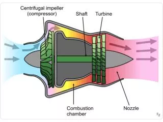
How do Generators (and Electric Motors) Function? • By the “interaction” of electric charge with magnetic fields. • This “interaction” is by a “Force” that tries to make the charge move (generator) or by the moving charge creating a “Force” that makes the magnetic field move (motor).
Magnetic Fields • Moving charge produces a magnetic field, B • A field is any physical quantity that takes on different values at different points in space. • For example, the temperature measured at the ground up to 30,000 feet provides a set of values, each corresponding to a height (position in space). This set of values is a temperature field.
Permanent Magnets – Where’s the Moving Charge? • Magnets have “permanent current”: • Some materials exhibit magnetic behavior due to the motion of electrons in orbit around nuclei. • Iron and other ferrous materials are magnetic because the electrons not only move in orbit around their nuclei, but also SPIN (sort of like rotation of the electron upon its axis*). Normally the electron spins are randomly oriented and so the magnetic field produced by each tend to cancel in bulk material. In iron these spin axis are aligned so that their effect is felt on a macroscopic level. • *A true description of electron spin requires quantum mechanics.
Electric Charge and Magnetic Poles • Electric charge can be positive or negative and can exist alone. • Magnetic poles can be North or South and always exist in pairs (e.g. North with South). • This is why magnetic fields “close” on themselves.
Bar Magnet The lines are a graphical representation of the magnetic field at each point in space. These lines are called “flux lines.”
Moving Charge in a Wire • Remember that moving charge produces a magnetic field too!
Generator • Moving a loop of wire in the presence of a magnetic field (B) produces a force (F) on the electric charge (q) in the wire (velocity of the wire is v). • The force is proportional to the product of the charge and the velocity of the charge (wire) and the magnetic field value F a qvB Force (proportional to) chg. X vel. X mag.fld.
Generator • The force pushes the electrons along the wire. • These electrons push nearby electrons along (remember like charges repel) and so on. We can get the same effect by keeping the wire stationary and moving the magnetic field (like spinning a bar magnet)
Generator Mechanical Work (kinetic energy) Moving Magnetic Field Moving Charge (Electrical current) • The mechanical (kinetic) energy of spinning the magnet creates motion of electric charge (electrical energy) that moves through the circuit. • We can replace the permanent magnet with another coil of wire conducting an electrical current (charge movement) that will produce the necessary magnetic field.
Wind Generators • Induction (Asynchronous) • Doubly Fed most common type • Requires gearbox • Synchronous (Direct Drive) • Permanent Magnet (small turbines) • PM is the technology of the future
Wind Generators - Types • Induction and Synchronous Generators can be used for wind turbine systems. • Induction generators can be used in a fixed-speed system or a variable-speed system • Synchronous generators are normally used in power electronic interfaced variable-speed systems. • Three types of induction generators are used in wind power conversion systems: • Cage rotor, • Wound rotor with slip control by changing rotor resistance, and • Doubly fed induction generators. • Cage rotor induction machine can be directly connected into an ac system and operates at a fixed speed or uses a full-rated power electronic system to operate at variable speed. • The wound rotor generator with rotor-resistance-slip control is normally directly connected to an ac system, but the slip control provides the ability of changing the operation speed in a certain range. • The doubly fed induction generators provide a wide range of speed variation depending on the size of power electronic converter systems.
Advantages of wind turbines with induction generators • Simple and cheap construction • No synchronization device is required • Attractive due to cost and reliability • Disadvantages • Not fast enough (within a few ms) to control the active power • Wind turbine has to operate at constant speed • Requires a stiff power grid to enable stable operation • May require a more expensive mechanical construction in order to absorb high mechanical stress since wind gusts may cause torque pulsations in the drive train and the gearbox. • Induction generators have high starting currents • Demand for reactive power • Need a reactive power compensator to reduce (almost eliminate) the reactive power demand of the turbine generators from the grid • It is usually done by continuously switching capacitor banks following the production variation (5–25 steps). • Connecting the induction generators to power system produces transients that are short duration, • Very high inrush currents causing both disturbances to the grid and high torque spikes in the drive train of wind turbines with a directly connected induction generator • Unless special precautions are taken, the inrush current can be 5-7 times rated current with a current peak of 18 times rated value – Results in large grid disturbances • Need a soft-start circuit to limit peak inrush to less than 2 times rated current • This damps torque peaks and reduces wear and strain on gearbox
Variable Speed Turbines • The generator is normally connected to the grid by a power electronic system. • For synchronous generators and for induction generators without rotor windings, a full-rated power electronic system is connected between the stator of the generator and the grid, where the total power production must be fed through the power electronic system. • For induction generators with rotor windings, the stator of the generator is connected to the grid directly. Only the rotor of the generator is connected through a power electronic system. • Advantage that only a part of the power production is fed through the power electronic converter. This means the nominal power of the converter system can be less than the nominal power of the wind turbine. • Nominal power of the converter may be 30% of the power rating of the wind turbine, enabling a rotor speed variation in the range of 30% of the nominal speed. • Controlling the active power of the converter, it is possible to vary the rotational speed of the generator and thus of the rotor of the wind turbines.
Exercise 9 1). Voltage is • The flow of charge • The power associated with charge • Is measured in units of volts • Is the electric potential energy per unit of charge • A. and C. • C. and D. • All the above
Exercise 9 2). Which statements about the electric power grid are true • The grid delivers ac voltage & current to your home. • The grid delivers dc voltage & current to your home. • Produces 3-phase voltages from a typical power plant. • A. and C. • B. and C. • C. only • B. only
Exercise 9 3). Reactive power • Is associated with the energy stored in the electric system. • Does work. • Is measured in units of volts. • Is only important in dc power systems.
Exercise 9 4). Motors and generators operate through the interaction of two magnetic fields, one of which may be produced by magnets. • False. • True. • Generators only. • Motors only.
Exercise 9 5). The major types of wind generators are: • ac and dc. • wound rotor and squirrel cage rotor. • synchronous and induction. • rms and peak.
Exercise 9 6). Synchronous when referring to generators (or motors) means • The machine must have a gearbox connecting it to the wind turbine rotor shaft. • The rotor and stator are locked together. • The rotor spins at the same speed as the internal magnetic field. • The rotor spins at the grid frequency of 60 Hz.
Exercise 9 7). Characteristics or properties of induction generators are • They are cheap to manufacture and relatively rugged. • They require a gearbox to connect to the turbine rotor. • The rotor spins at a speed slower than the internal magnetic field. • All the above. • A. and B. only
Exercise 9 8). Disadvantages of induction generators are • The machine must have a gearbox connecting it to the wind turbine rotor shaft. • They require large starting currents. • They require reactive power from the grid. • They are inexpensive to manufacture. • All the above. • B., C., and D. • A., B., and C.
Power Semiconductor Devices Insulated Gate Bipolar Transistors, IGBTs, and Integrated Gate Controlled Thyristors, IGCTs are the main types of devices used in power converter equipment for large wind turbines. Diodes are used in all electronic equipment. Note: IGCTs are a type of GTO.
IGCT Structure Cathode top view of a GCT die • Operation and limits of thyristors • Symmetric and Asymmetric • dv/dt limits • di/dt limits • Gating (triggering) • Qualitative physical behavior during switching • Packaging and Heat Flow IGCT is Integrated Gate Controlled Thyristor
NPT PT FS IGBT Modules Operation and Limits of IGBTS IGBT is Insulated Gate Bipolar Transistor
Power Converters • Modern power converters are all solid state electronic systems composed of high-powered semiconductor switches and storage circuit elements. The converters and associated control electronics can fit into the nacelle in some small turbines to large cabinets on the ground in large turbines. Example of power converter rated for 40 kW. (The converter is about 14” across)
Power Converter Definitions • An electronic system that converts ac voltages and currents to dc waveforms is called a Rectifier. • An electronic system that converts dc voltages and currents to ac waveforms is called an Inverter. • An electronic system that converts dc voltages and currents to another dc value is called a dc-to-dc Converter. Often all these types of systems are generically called Power Converters.
Wind Turbine Topologies Most small turbines are designed with a synchronous generator and no gearbox. Partly due to the serious maintenance issues with gearboxes, turbine designers are moving to synchronous generators for all size turbines. Another advantage to the synchronous generator systems is that all the power produced is processed through power electronic converters, thus providing considerable opportunities for fine control of system parameters. Most large turbines are designed with an induction generator and the necessary gearbox
FULL RATED POWER ELECTRONIC INTERFACE WIND TURBINE SYSTEMS • Cage induction generators and synchronous generators can be integrated into the system by full rated power electronic converters. • A passive rectifier and a boost converter are used in order to boost the voltage at low speed. • It is possible to control the active power from the generator. A grid inverter interfaces the dc-link to the grid. • It is also possible to control the reactive power to the grid. • The system is able to control reactive and active power quickly and then the turbine may take part in the power system control.
Traditionally, wind turbines are not required to participate in frequency and voltage control. In recent years, attention has been increased on wind farm performance in power systems. • Consequently, some grid codes have been defined to specify the requirements that wind turbines must meet in order to be connected to the grid. • Examples of such requirements include the capability of contributing to frequency and voltage control by continuously adjusting active power and reactive power supplied to the transmission system, and the power regulation rate that a wind farm must provide. • Some of the requirements can be dealt with by implementing control schemes in certain types of wind turbines, such as reactive power control with wind turbines having power electronic converters. • Many research activities have been conducted in this area. • Described are main requirements, turbine performance assessments, and some possible methods for meeting the requirements.
Frequency and Active Power Control • The frequency of a power system is proportional to the rotating speed of the synchronous generators operating in the system. The generators in the same ac system are synchronized, running at the same speed. • Increasing the electrical load in the system tends to slow down the generators and reduce the frequency. The task of frequency control of the system is to increase or reduce the generated power so as to keep the generators operating in the specified frequency range. • However, renewable resources can only produce when the source is available. For wind power, this is when and where the wind blows. This characteristic is important when the amount of wind power covers a large fraction of the total demand for electricity energy in the system. • In order to be able to increase the power output for frequency control, a wind turbine may have to operate at a lower power level than the available power, which means low utilization of the wind energy resources. • One way to improve the situation may be the use of “energy storage” technologies, such as batteries, pumped storage, and fuel cells, though the speed of response will vary depending on the energy storage technology. • So far large-scale, cost-effective energy storage technologies are yet to be developed.
Reactive Power Control • Conventional reactive power concept is associated with the oscillation of energy stored in capacitive and inductive components in a power system. Reactive power is produced in capacitive components and consumed in inductive components. • Asynchronous generators can either produce or consume reactive power by controlling the magnetizing level of the generator, i.e. a high magnetizing level results in high voltage and production of reactive power. • The current associated with the reactive power flow causes system voltage drop as aforementioned and also power losses. Furthermore, large reactive currents flowing in a power system may cause voltage instability in the network due to the associated voltage drops in the transmission lines. Therefore, reactive power control is important. • The induction generator based wind turbines are a consumer of reactive power. • To minimize the power losses and to increase voltage stability, these wind turbines are compensated to a level depending on the requirements of the local utility or distribution company. • For wind turbines with PWM converter systems, the reactive power can be controlled by the converter. For example, these wind turbines can have a power factor of 1.00 and also have the possibility to control voltage by controlling the reactive power (generation or consumption of reactive power).
Voltage Quality Assessment • Assessment of the impacts from integrating wind turbines may be performed according to the methods given in the IEC 61400-21 /2/ to determine the acceptability of such integration. • These include: • Steady-state Voltage • Flicker (voltage fluctuations) • Harmonics
Exercise 10 1). Inverters are power converter circuits that • Convert wild ac from a wind generator into dc voltages and currents. • Convert dc voltages and currents into ac ones compatible for the electric grid. • Convert dc voltage at one value to a dc voltage at another value. • Are never used in wind energy systems.
Exercise 10 2). Insulated Gate Bipolar Transistors (IGBTs) are often used in wind power electronic systems. Another device used is: • Power MOSFETs. • Light Emitting Diodes (LEDs). • Bipolar Junction Transistors (BJTs). • Integrated Gate Controlled Thyristors (IGCTs).
Exercise 10 3). List the statements that are true. • Wind turbine designs are moving to synchronous generators so that gearboxes are not needed. • Control of the reactive power associated with a wind turbine is not important. • The task of frequency control of the wind energy system, with asynchronous generators, is to increase or reduce the generated power so as to keep the generators operating in the specified frequency range. • Integration of wind turbines into the grid require attention to voltage levels, voltage fluctuations, and harmonics (voltages not at 60 Hz) introduced into the grid.