DEMO / FPP Main Sub-systems
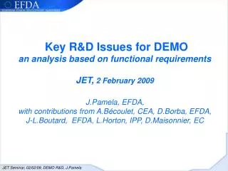
Key R&D Issues for DEMO an analysis based on functional requirements JET, 2 February 2009 J.Pamela, EFDA, with contributions from A.Bécoulet, CEA, D.Borba, EFDA, J-L.Boutard, EFDA, L.Horton, IPP, D.Maisonnier, EC. MAINTAINANCE. Remote. Handling. System. Cryostat. Poloidal Field Coil.

DEMO / FPP Main Sub-systems
E N D
Presentation Transcript
Key R&D Issues for DEMOan analysis based on functional requirementsJET, 2 February 2009J.Pamela, EFDA, with contributions from A.Bécoulet, CEA, D.Borba, EFDA, J-L.Boutard, EFDA, L.Horton, IPP, D.Maisonnier, EC
MAINTAINANCE Remote Handling System Cryostat Poloidal Field Coil Toroidal Field Coil Breeding Blanket Power Conversion System Supply Electric Power D + T + ashes Heating and to the Grid Pumping Current Drive D + T T Systems Isotope T Separation ELECTRICITY PRODUCTION He LONG PULSE / C.W. He FUEL CYCLE Li D D Re-circulating electric power to the H&CD system PeHCD DEMO / FPP Main Sub-systems
DEMO Key step before the first generation of FPP’s: => qualify all components and processes required for the first FPP => prepare forenvironmentally friendly power production (reduced/low activation materials) => prepare for cw operation Reactor grade functional requirements are likely to constitute key drivers in DEMO design and R&D: • Closed Fuel cycle • Efficiency of electricity production • Maintainability • Reliability DEMO R&D needs (beyond the well known breeding blanket and materials issues) are analysed here in light of these functional requirements
Only efficiency and availability (reliability and maintainability) addressed in this talk
1- Efficiency of electricity production Cost of electricity (CoE) studied in the frame of the Power Plant Conceptual Studies (courtesy D. Ward, UKAEA): r= discount rate F = learning factor A = plant availability ηth = thermodynamic efficiency Pe = unit size βN = normalised plasma pressure N = multiplier of the density compared to the density limit Overall current drive efficiency ηCD not explicit in formula. Non-linear impact on overall efficiency through re-circulating power
Recirculated power and plant efficiency Example: steady state tokamak power plant (D.Ward, EFDA Task TW6-TRP-002) • R=7.5m, a=2.5m, B=5.86T, I=19.4MA • hybrid mode of plasma operation (advanced H-mode): H=1.3 and bN=3.6 • high current drive efficiency 0.38 1020 A/Wm2 (yielding about 0.05 A/W at n=1.03 1020 m-3) that assumes 2MeV Neutral Beams (technology well beyond anything available or under development today) • bootstrap current fraction 0.54 => 9 MA current remain to be driven • 180 MW of H&CD power need to be coupled to the plasma • high temperature He cooled blanket and divertor assumed => 50% thermodynamic efficiency
Recirculated power and plant efficiency Example (ctd): 2.4 GW fusion power converted into 1.56 GW of gross electric power (assuming 1.18 energy multiplication factor in the blanket) 1/3 of gross electric power need to be recirculated within this plant to • pump He (~200 MW), • power the H&CD systems (~300 MW with veryoptimisticηCD) and • operate the balance of plant (~60 MW) MAIN PENALTIES: HELIUM COOLING AND H&CD
Key parameters driving cost of electricity Not addressed in this talk and not relevant to DEMO: r and F and Pe Parameters addressed in this talk: • βN and N => tokamak physics R&D • hCD => tokamak physics and H&CD technology R&D • hth => high coolant temperature => R&D on materials and cooling techniques • Magnets => potential gain on efficiency (balance of plant power) and on capital cost with High Temperature Supraconductors (HTS) • A => Maintainability and Reliability driven R&D
High βN and N => tokamak physics requirements (1/8) Rationale: Fusion power strong function of - density (~n2) - pressure High βN also provides high bootstrap current fraction which reduces requirements on current drive
With additional power: Steep edge pressure gradient: H-mode scenario Separatrix distance from axis H-mode pedestal X-point Divertor High βN and N => tokamak physics requirements (2/8) Standard tokamak operation: the H-mode scenario pressure L-mode distance from axis
With additional power: Steep edge pressure gradient: H-mode scenario H-mode pedestal High βN and N => tokamak physics requirements (3/8) Standard tokamak operation: the H-mode scenario • Advantages: • Natural plasma state in the divertor tokamak configuration with additional heating power. • Minimal control requirements. • Disadvantages: • Limited plasma pressure achievable bN ~ 2-3. • - Instabilities associated to large edge pressure gradient (“ELMs”) pressure L-mode distance from axis
High βN and N => tokamak physics requirements (4/8) Advanced Tokamak modes of operation with internal transport barrier H-mode plasma with an ITB • Advantages: • Improved core confinement and better stability properties leading to higher plasma pressure achievable bN ~ 4, as required for high DEMO efficiency. • Challenges: • Operation in steady state with advanced control techniques: • Plasma Profiles • Plasma Instabilities Layer of reduced transport H-mode pressure L-mode distance from centre ITB reviewed in R. Wolf PPCF 2003, Connor Nuc. Fus 2004, Challis PPCF 2004
AUG DIII-D JT-60U JET 4 unstable 3 bN Advanced H-modes (Hybrids) 2 Standard H-mode 1 2 4 6 Pressure peaking: p0/<p> High βN and N => tokamak physics requirements (5/8) Advanced Tokamak mode of operation with internal transport barrier Operation in steady state requires advanced control techniques of the plasma profiles (pressure) This may constitue a major challenge in a burning DT plasma
bN=3.3 5 1.0 0.8 0.6 current [MA/m2] 3 0.4 2 0.2 1 Normalised radius High βN and N => tokamak physics requirements (6/8) Advanced Tokamak mode of operation with internal transport barrier - Operation in steady state requires advanced control techniques of the plasma profiles (current) Field line twist in a tokamak: q q=2 q=1 Significant off-axis current drive is required to maintain qmin>2, in addition to the off-axis current produced naturally by the pressure gradient
UNSTABLE Coils STABLE WITH CONTROL STABLE High βN and N => tokamak physics requirements (7/8) Advanced Tokamak mode of operation with internal transport barrier Operation at high pressure (βN> 4) requires qmin > 2 and active control of plasma instabilities.
High βN and N => tokamak physics requirements (8/8) Operation at high density (n/nG > 1) - The empirical Greenwald density limit describes well the experimental results. • DEMO designs rely on operation close or above the empirical Greenwald density limit n/nG = 1.2 to 1.5
Current drive efficiency hCD (1/7) Three steps1- conversion of electric power into power launched in plasma: conversion efficiency hconv2- coupling of launched power to plasma: coupling efficiency hcoupl3- current drive efficiency (current driven per power unit coupled to plasma eCD)Penet = Pegross - PeHCD – PeBoP = Pegross - ICD/hconvhcoupleCD – PeBoP
H&CD Conversion and Coupling Current drive efficiency hCD (2/7) hconv = Plaunched / (Psource+Paux ) Paux Auxiliary PS, Cooling, pumping, cryogenics, … Coupling source transmitter Plaunched Psource Pcoupled Cooling, pumping hcoupl = Pcoupled / Plaunched Plost
Current drive efficiency hCD => tokamak physics and technology requirements (3/7) Wall-plug to coupled power efficiency CONVERSION COUPLING (Technology) (Physics) CD efficiency (DEMO-like plasmas) PHYSICS high NNBI high Low (20-30%) low-medium ICRH medium Medium (40-50%) LHCD medium high Medium (30-40%) high ECRH low-medium Low(20-30%)
Current drive efficiency hCD (4/7) ‘Wall plug’ efficiency of JET NB heating systems • Neutral Beam power to plasma: 25MW • Total power consumption: 116MW • HV beam acceleration : 99MW; Regulation/switching losses on HVPS: 12.6MW; Ion source: 2MW; Cooling: 0.6MW; He refrigerator: 0.65MW; Other: 0.5MW • Overall conversion efficiency: 25MW/116MW = 22% • Main losses / main opportunities for improvement: • neutralisation efficiency (~ 0.35 for positive ions) and • geometric beam transmission (~ 0.7, -> 0.78) Courtesy TTC. Jones, UKAEA
Current drive efficiency hCD (5/7) Neutralisation efficiency for NBI improvement with negative ion beams Foreseen efficiency range of “advanced” neutralisation methods applicable to negative ions (photo-det. or metal vapour), Very demanding / remain to be developed JT60U ITER AUG JET D2 gas neutralier
Current drive efficiency hCD (6/7) ‘Wall plug’ efficiency of Tore Supra ECRH system • Power to plasma (full system): 2.4 MW • Total power consumption: 10.7MW • Overall conversion efficiency: 2.4 MW/10.7 MW = 22% • Main losses: Gyrotron, tetrode series regulator, HV power supply • Opportunities for improvement: • Gyrotrons with depressed collector • ( e.g. 170 GHz 1 MW tube developed by Japan for ITER reach 55% efficiency with depressed collector; but… still insufficient => multi-stage collectors ?) • solid state HVPS Courtesy R. Magne, CEA
There is a serious H&CD efficiency issue:wall-plug-to-coupled-power efficiency of present systems in the range 20-40%, while 60-70% are required for a c.w. DEMO
Thermodynamic efficiency hth Optimisation of temperature of coolant (1/7)MATERIALS • MATERIAL DEVELOPMENT IS FUSION SPECIFIC • A NUMBER OF ISSUES STEMS DIRECTLY FROM THE PROPERTIES OF THE 14 MeV NEUTRONS AND THE REQUIREMENT FOR AN ENVIRONMENTALLY ACCEPTABLE ENERGY SOURCE: He and H production (14 MeV DT fusion neutrons) Strong requirements in terms of structural properties Heat sink & Armour Materials Reduced / Low activation OTHER REQUIREMENTS ON MATERIALS ARE MORE RELATED TO REACTOR GRADE FUNCTIONAL REQUIREMENTS, IN PARTICULAR HIGH TEMPERATURE OPERATION
Thermodynamic efficiency hth Optimisation of temperature of coolant (2/7) • High Thermodynamic Efficiency: • Towards High Temp. of Coolant (He-cooling as reference option) Strong drive for materials R&D • DEMOBLANKET (~80 dpamax, He ,H): reduced activation Ferritic/Martensitic & Ferritic Steels • EUROFER: Tmax ~550 0C • ODS-EUROFER: Tmax ~650 0C • ODS Ferritic Steels: Tmax ~750 0C DIVERTOR (40 dpamax, He, H): Refractory W-alloys under assessment Armour materials: W-Y2O3, W-Si-Cr, W-TiC Structural materials: W-Ti, W-Ta W-V Temperature upper limit determined by Creep Strength Temperature upper limit Determined by Recrystallisation
Thermodynamic efficiency hth(3/7) 105 h 102 h 5500C 6500C 7500C 8500C 9500C Upper Temperature Limit for Structural steels Estimated Upper Limit on the Basis of a Creep strength of 100 MPa for ~50,000 Hours
Thermodynamic efficiency hth(4/7) Pressurised Water Low-medium Temperature He Relatively narrow Temperature Window Lower Temperature Limit as well : Radiation Induced Increase of Ductile-Brittle Transition Temp. DBTT Fission Reactor Data Conventional 9% Cr Steels & EUROFER: Significant loss of Fracture toughness at ~300 0C Operation at higher temperature, above 500C might help Fusion Relevant He Production might increase further the Loss of Fracture Toughness: Recent SINQ Results at ~10 dpa, 60-80 appmHe/dpa
Thermodynamic efficiency hth(5/7) W W-26%Re W-La2O3 Upper Temperature Limit for W-alloys (divertor) Severe Plastic Deformation & Alloying: To Improve the Fracture Toughness of W and W-alloys Annealing 1 hour 835 0C Initial Microstructure Non-Affected Loss of Fracture Toughness 1200 0C Unacceptable Recrystallisation Recrystallisation resistance is unacceptably affected New alloys are being developed : W-Ti, W-V for structural applications, W-Y2O3, W-Si-Cr, W-TiC for armour. Behaviour under irradiation to be tested in a second stage R. Pippan et al.
Thermodynamic efficiency hth(6/7) 10 MW/m2 W tile: max. allow temp. 2500°C max. calc. temp. 1711°C DBTT (irr.): 700°C Thimble: max. allow. temp. 1300°C max. calc. temp. 1170°C DBTT (irr.): 600°C ODS-Eurofer: He-out temp. 700°C He-in temp. 600°C DBTT (irr.): 300°C He-cooled Divertor Concept for DEMO Heat Flux Fatigue Testing ~10 MW/m2 ~100 cycles Infra-Red Image during testing P. Norajitra et al., FZK
Thermodynamic efficiency hth(7/7) Optimisation of temperature ofcoolant is a complex issue • In the long term, high temperature cooling might be a must (He>550ºC), • to increase plant efficiency (although the balance between increased complexity and large circulating power required for high T operation might offset the gain) • but maybe also to avoid deterioration of materials strength (DBTT). • It is essential to continue R&D on He-cooled in-vessel components (Materials, welding and joining techniques, He technology). • However, it is not clear whether all He-related technologies will be mature enough for application on DEMO. • Helium is today a by-product of petroleum industry; it is a finite resource on earth. • It is therefore appropriate to consider back-up options, e.g. water-cooled DEMO, which requires specific R&D.
Overall plant efficiency: High Temperature Superconductors (1/2) • PPCS and DEMO studies show magnets contribute to about 1/3 of the cost of plant ! • In addition 4 K cooling increases • plant complexity & cost • recirculated power (about 10 MW for the plant mentioned previously) • …and it impacts reliability. • Nb3Sn used on ITER with 11.8T limit on TF conductor • Prospect to extend use of Nb3Sn to 13.5T limit => increased margins/performance (test on-going on Dipole) • But Nb3Sn requires low T operation 4K (Liquid He) • Potential gain in operating at higher T (reduced recirculated power): • Ultimate target is for HTS working above 80K to allow liquid Nitrogen as coolant instead of liquid He and simplify cryostat
Overall plant efficiency: High Temperature Superconductors (2/2) Potential candidate YBCO for TF coils, operation at > 65K … still a long way to go in terms of conductor performance and development
2- Availability DEMO shall qualify components and processes in reactor relevant conditions Machine availability is therefore a key parameter. MTBF: Mean Time Between Failure (or Mean Time Between Replacement) MTTR: Mean Time To Repair (or Mean Time To Replace) In DEMO, MTTR for all in-vessel components shall be minimized but will remain long (several months) MTBF should therefore be considerably longer to guarantee a high availability => hence high requirements on Maintainability (minimise MTTR) & Reliability (maximise MTBF)
3- Maintainability (1/2) Maintenance => significant impact on Design • RH procedure and equipment • RH manual (requirements for components to be handled) • suitable reactor layout (access, transfer of components…) • A key issue: blanket maintenance • ITER blanket segmentation not reactor relevant (too many modules replacement too long). • No satisfactory solution available. One option considers the transfer of large “banana-like” segments from top vertical ports => R&D will be precisely defined at the end of DEMO Conceptual Studies (which remain to be launched …)
3- Maintainability (2/2) Local inspection and maintenance may require special systems in addition to fixed units Picture: the AIA (Articulated Inspection Arm) has just completed its first inspection in Tore Supra under high temperature and UHV conditions.
4- Reliability (1/11) Some of the main issues expected: • Reliability of tokamak operation: avoidance of disruptions and other events • Wall materials life-time: • Plasma compatibility with relevant metallic wall materials => R&D Physics • R&D on plasma facing materials • minimisation of power to divertor targets • Complexity of in-vessel systems • 14 MeV neutron fluxes, up to 80dpa before maintenance! => R&D on materials and component Avoid copper as a heat sink in PFCs and in H&CD components under neutrons (swelling & activation) • Complexity of H&CD systems(significant part of the plant if large CD required !) • Diagnostics and control requirements
4- Reliability (2/11) Reliable Tokamak Operation Avoidance of Disruptions • “Disruptions”, abrupt termination of the plasma, need to be avoided in DEMO • Why ? • transient loads on plasma facing components (erosion/melting) • forces on vessel and in-vessel components • significant loss of availability (long recovery from disruption) • How ? • disruption avoidance (precursors) and mitigation • operation away from stability limits(avoid too ambitious plasma operation) Infrared view of the vessel during a disruption at JET showing the thermal loads in the plasma facing components
ITER JET 4- Reliability (3/11) Compatibility between plasma operation and relevant wall materials • Carbon will NOT be used as plasma facing material on DEMO • Erosion • T trapping • loss of thermal conductivity under irradiation • Challenging development of plasma scenarios compatible with metallic walls • avoidance of edge localised modes (ELMs) • control of impurities • optimisation of plasma radiation etc. • ASDEX-Upgrade W-experiment • JET ITER-like Wall experiment (Be and W) • ITER W-Divertor foreseen for DT operation
Plasma PRadiated PLOSS Targets 4- Reliability (4/11) Tokamak Operation Operation with high radiation fraction > 90 % Reduction of power loads on Plasma Facing Components will increase their lifetime This drives tokamak operation towards highly radiative modes => Impurity seeding of both divertor and core plasma …radiation levels limited by: dilution of the fuel; impurity accumulation and impurity sputtering of the tungsten target
Plasma PRadiated PLOSS Targets 4- Reliability (5/11) Tokamak Operation and first wall/divertor life time If very high radiation fraction cannot be obtained routinely in a robust plasma scenario, there will be no other choice but reducing plasma performance to keep power loads at reasonable levels
4- Reliability (6/11) In-vessel components: blanket
4- Reliability (7/11) Swelling & loss of Conductivity => Avoid Copper or use DS Cu alloys Swelling under irradiation Swelling and Loss Electrical Conductivity under irradiation J. Nucl. Mater. 233-237 (1996) 127-137 J. Nucl. Mater. 191-194 (1992) 386-390
(in addition, impact on waste) Gamma Dose Rate versus Decay Time (1) Activation => Use of Copper will be banned from DEMO and reactors plasma vicinity Irradiation condition : 5 years in the First Wall neutron spectrum • Waste Limits (2) • High Level Waste limit: 2E-2 Sv/h • Medium Level Waste limit: 2E-3 Sv/h • Low Level Waste limit: 1E-4 Sv/h • Hands-on Level limit: 1E-5 Sv/h • UKAEA FUS 509. Handbook of Activation Data Calculated Using EASY-2003 • After R. Lindau et al. Fusion Engineering and Design 75–79 (2005) 989–996
4- Reliability (8/11)Copper Copper broadly used today for components subject to neutron bombardment:- as heat sink material in plasma facing materials- to fulfill all high (electric/thermal) conductivity requirements in H&CD systems- all NB actively cooled components (source, accelerator, neutraliser, dumps, beam scrappers, duct protections…) - LHCD couplers - ICRH antenna straps and transmission linesReplacing copper (or at least drastically limiting its use in case swelling and loss of conductivity are acceptable) is a major and long-lead R&D challenge which is not sufficiently addressed today
4- Reliability (9/11) Operation and plasma control No Physics R&D on DEMO Most probably : • a limited number (possibly a single one) of very robust modes of plasma operation with limited control requirements • a single H&CD system • minimised number of diagnostics for operational purposes only • no or very few active diagnostics => Integrated DEMO conceptual studies should define rather early a set of constraints on plasma operation and control (including H&CD and diagnostics) to guide the development of plasma scenarios on present devices and ITER
Reliability (10/11)H&CD systems Improving reliability requires significant R&D to reduce complexity and improve individual sub-systems …for example on Neutral Beams: • Cs consumption in source (Cs-free solution?) • Large number of sub-systems requiring remote handling for maintenance • Specifically demanding maintenance of source • Gas pressure too high (losses, pumping requirements) • Injector conditioning techniques (impact on availability!) • HV breakdown avoidance/mitigation • Find substitute to copper • etc….
Final comments onReliability (11/11) JET statistics on injected NB Power (courtesy TTC.Jones UKAEA) maximum nominal power 25 MW (attention is brought to the fact that the requested NB Power spans a broad spectrum from 5 to over 20 MW) Reliability == More Margins !!
Summary on efficiency and availability driven DEMO R&D needs • (Breeding Blanket not addressed here but of course an essential component) • Materials for in-vessel components: • He production by 14 MeV neutrons and structural or functional requirements drive fusion specific R&D • High T operation (required to optimise CoE) puts severe additional requirements on materials • Limit the use of / find a substitute to copper as heat sink material • Maintenance: a very significant programme of RH will be needed but can be defined only once DEMO Conceptual Design is available
Physics/Tokamak operation • Significant improvement in tokamak operation reliability required (avoidance of disruptions, ELMs etc.) • Minimisation of power loads on plasma facing components (e.g. high radiative fraction OR modest performance) • Compatibility between plasma scenarios and metallic wall materials • A GAP: no Tokamak (operating or foreseen, not even ITER) will provide demonstration of operation at DEMO/reactor relevant first wall temperature ! • Development of plasma scenarios towards high performance (bN, density) but with limited/reasonable current drive and control requirements => A TRADE-OFF BETWEEN PERFORMANCE AND RELIABILITY WILL BE NECESSARY
Diagnostics • Limited in number as a result of an integrated development of plasma operation and control • Robustness: radiation resistant, high temperature, limited maintenance / requires significant and long R&D efforts • Heating and Current Drive systems: The needs for R&D in this area have always been dramatically underestimated and under-financed; mistakes of the past should not be repeated R&D efforts have been/are driven by ITER on beam energy (negative ions) or gyrotron frequency (170 GHy for ITER) but little is done otherwise => Significant simplifications and developments required • Overall efficiency of H&CD systems (from plug to plasma) has to be increased from 20-40% today to 60-70% • Duty cycle (from 10’s of seconds to cw operation; reduced maintenance needs) • very high reliability under nuclear operation