Download

1 / 22
220 likes | 369 Vues
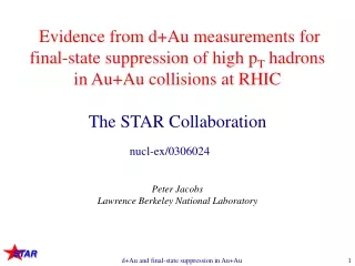
Inner Sector Upgrade for the TPC Jim Thomas Lawrence Berkeley National Laboratory. UCLA Upgrades Workshop December 14 rd , 2011. Au on Au Event at CM Energy ~ 130 GeV*A. The STAR TPC has taken beautiful data, without a glitch, since the very first day of RHIC operations.

E N D
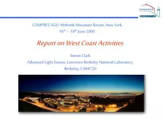
Inner Sector Upgrade for the TPCJim ThomasLawrence Berkeley National Laboratory UCLA Upgrades WorkshopDecember 14rd, 2011
Au on Au Event at CM Energy ~ 130 GeV*A The STAR TPC has taken beautiful data, without a glitch, since the very first day of RHIC operations Data Taken June 25, 2000.
The TPX Upgrade (TPc electronics eXtended) • Works well • 5% deadtime at 1 kHz (pp) • Max rates ~ 3 kHz • Enables high level triggers for use in high luminosity running • Better Signal to Noise than old electronics • Old electronics: • ~30 ADC counts was the highest peak of the cluster • ~1.5 ADC RMS • S/N is 30/1.5 = 20 • New electronics: • ~22 ADC peak • ~0.7 ADC RMS • S/N (22/0.7) = 30 New muscle for an old detector and a tremendous success
Outlook for the Future of the TPC • Q: Can we rely upon the TPC for another 10 or 15 years? • A: Probably not • Timescale • eRHIC physics starts in 2022 • The TPC is ideal for 5 GeV e- beam operations • See past talks by Ernst and others about physics & kinematics • Fortunately, not so ideal for 20 GeV operations … so there is a logical end of the life for the TPC about 15 years from today • Strengths and Weaknesses • Gas system good, but relies upon “home made” electronics • Field Cage good, two permanent shorts, more on the way? • Other systems good enough, could always be improved • Electronics excellent, recently upgraded • Inner sectors need work
TPC Sector Detail – Aging of the Anode Wires • Gating Grid • Ground Shield • Anode • 4 mm pitch, no field wires • Spacing: inner outer • Pad Plane
Our concern is about the inner sectors • The inner sectors are affected the most due to 1/r2 distribution of charge in the TPC • We expect a gain shift on anode wires due to charge, gain & dirt • Figure of merit is 1 mC / cm • Malter effect on the cathodes due to build up of insulating oxide layers … leads to breakdown • No figure of merit Aging of the anode wires and tripping on the cathode wires
Anode Aging – should see annual gain shift • Aging on the anode wires is very hard to measure • It is like global warming … the systematic errors are larger than the annual trend • We have made many measurements and surveyed the literature; the results don’t tell a consistent story • During the pp500 run, STAR accumulated 10 C of charge on the inner sectors of the TPC • Approximately 1600 m of wire • During the 2009 pp200 run, STAR accumulated another 12 C • Prior to 2009, we estimate that STAR accumulated 40 C of charge on the inner sectors 10 C pp500 +12 C pp200 200 C increments Y. Fisyak
2009 was a bad year • We experienced a large number of trips on the inner anode wires during the pp 500 run … the concern is broken wires and blown electronics • Our response was to lower the voltage on the anode wires from 1170 1135 1100 volts over the course of 3 years • The gain has been changed from 100% 66% 42% and everything seems to work (surprise!) • Doom and Gloom … spawned many measurements & reviews • Perhaps we over-reacted. We have run much higher beam currents in 2010 and 2011 and did not have a problem, however we never put the gains back to old (100%) settings • Currently, I think it is possible that the beam was poorly tuned in 2009 and so we had very high background as well as a normal rate of aging and Malter effects • The bottom line is that we cannot accurately predict the rate of aging or the occurrence of breakdown in the TPC. Better beams and lower gains have temporarily solved the problem
TPC Lifetime Review – 2009 Action Items • The Committee recommends running with lower gains in all future pp running and possibly HI. Study impact on physics. • Take calibration runs at the end of the 2009 run to determine aging on wires relative to the beginning of the run. Also study lower gains on the TPC sectors so we can choose a new gain setting for future running. Check Dedx and tracking quality. • Build a mount for the sector insertion tool. We have a preliminary design from LBL. (not done) • Remove one sector and replace it with a spare sector in the summer of 2010. Study aging on these wires. (not done) • Create a cost and schedule for winding new Anode and Cathode (aka Ground) wires. Include a fix for grid leak, if possible. Determine availability and status of the BNL wire winding machine. Establish a laboratory in which to work. (more)
Sector Repair is possible but not a trivial task Sector Installation & Tooling
The biggest job: Winding new grids Cost: ~ 1 M$ Schedule: ~ 1 Year Good wire winding machines are rare. The original wire winding machine in Berkeley has been dismantled. Fortunately, there is one still available at BNL. Techs would have to be trained.
60 cm 190 cm TPC Sector Detail • 24 sectors • 12 on each side • Large pads for good dE/dx resolution in the Outer sector • Small pads for good two track resolution in the inner sector Fill in the missing pad rows? (XZB and JCD)
If we wind new grids … why not do even more? • Jamie and Zhangbu suggested that this would be a good time to fill in the missing pad rows on the inner sectors • more pad rows • improved tracking for low angle tracks that exit through the endcap ( 1.25 < < 2 ) • This will require that we make new pad planes and Al “strong backs” to support the pad plane • This is a wonderful idea! (for many reasons) • If we have new Al “strong backs” then we can prepare the new sectors in advance and install them in one summer shutdown • The original plan was to take the sectors out one at a time, repair, and replace it. This would have shutdown RHIC/STAR for a year. • Now the work can be done on a more relaxed schedule • A smaller team of technicians over a longer period of time • A good opportunity to fix the grid leak problem (at least ½ of it) • Use the ALICE solution with a biased barrier on sector boundaries • Add more large diameter wires in the vicinity of the last wire • Perhaps rebuild ABDB board w/possible breakdown problems
Example: The Inner Sector Pads are too small • The outer sector pad size was chosen to match the diffusion limit of P10 • Width (pitch) in the outer sector is 6.7 mm • Tonko has measured an average of 3 pads hit per cosmic ray track • The inner sector pads were deliberately made smaller (for no good reason except that people expected it, HW) • Width (pitch) in the inner sector is 3.35 mm • note different pad plane to anode wire spacing & gain (2 mm vs 4 mm) • Tonko has measured an average of 4 pads hit per cosmic ray track • It seems quite reasonable to increase the size of the inner sector pads so that an average of 3 pads are hit per cosmic ray track • Note, this does not mean 6.7 mm pitch is best … due to different gain and wire geometries in the inner and outer sectors • Real simulations are required … but not difficult Roy Bossingham’s simulations of the old pad geometry (3) agree with Tonko (~2)
The full range of possibilities … (numbers, not science) • The outer sectors are 6.7 mm x 20 mm (pitch) • The inner sectors are 3.35 mm x 12 mm (pitch) • The full range of possibilities for the new inner pad plane • Height from 12 mm to 20 mm (nb: 0.5 mm gap on all edges) • Note: only 12, 16 and 20 mm match anode wire spacing (3x, 4x, 5x) • Width from 3.35 to 6.7 mm • Translate to number of electronic channels • 6,650 channels if 3.35 by 12 mm (50 rows) • 2,000 channels if 6.7 by 20 mm (30 rows) • Currently 1750 channels in 13 rows (widely spaced at ~5 cm) • Range is from 1 to 4x number of channels (for hermetic coverage) • 1x would accommodate 6.7 x 20 pad pitch (87% coverage, 30 rows) • 2x would accommodate 4.8 x 16 pad pitch (100% coverage, 40 rows) • 3x would accommodate 4.2 x 12 pad pitch (100% coverage, 50 rows) • (For reference, ALICE uses 4x7 pads, but note that Neon-CO2 has better diffusion characteristics so we expect smaller pads in their case) Optimize this number for cost and engineering factors
Optimizations (again, note … not science) • A primary task is to optimize the density of electronics • will it fit? • can we afford it? • Perhaps the most difficult part of this project is to solve the “connection” problem between the FEE cards and the pad plane • traces on the pad plane • connector technology (aka packing density does not follow Moore’s law) • Tonko “feels” that 2x to 3x number of previous channels is possible with high density connectors and new FEE boards • New PASA and Altro chip designs are available (or in the works) • Packing density per FEE board has not changed, still 2 large chips and 32 channels per chip/board. Power consumption likely to go up (not down) just because we try to do more onboard. Etc.
R&D Physics and Instrumentation R&D • Optimize number of rows to match available funds & Eng. factors • Optimize pad size for greatest physics return • Join existing R&D efforts for PASA and Altro chips Technical Challenges (R&D by another name) • Pad plane design – traces & connector technology, alignment • Winding large wire planes … an art rather than a science • Factory – assembly line, QA and efficiency This is not an R&D project for Georges Charpak … but our technical teams will find it to be very challenging and exciting. They will enjoy it. This is a blessing in disguise because it will allow us to spend our most creative resources on other projects
Cost and Schedule • design pad planes • Old design was dominated by cost of the design and layout of the pads … this has changed dramatically with the use of new computer aided design tools. Now, not a big deal. • produce pad planes • Production costs are not large, however, learning to glue the pad plane onto the Al strong backs and align them properly is the dominant cost • glue and align pad planes • $250 K (for all three steps) • wind wire grids • $1 M • design Al strong backs (aka sectors) • design already done, needs draftsman to translate into 3D CAD • fabricate Al strong backs • detailed cost estimate is needed, but not likely a cost driver • design new electronics • note new chips required • fabricate new electronics 3 good technicians 1 engineer 1 year < $2 M $2 M
Conclusions • The TPC is a beautiful detector. It is a credit to the original design that it has lasted so long and offers so many options for continued operation beyond the original specifications. • The TPC has performed well in 2010 and 2011 • Wire (slow) aging isn’t the immediate problem. • HV channel trips (fast aging) may be the greater problem … but lower gain operations has helped • We will have to rewire the inner sectors … one of these days • Building new pad planes and Al strongbacks is a very good way to do the project • It allows for parallel operation: build instrumented sectors in advance and install them in one shutdown • Hermetic coverage with 40 rows on the inner sector is possible • Less expensive, fewer people, lower risk, better science This is a golden opportunity to design a new inner pad plane that extends the physics reach of the detector
Accumulated Charge – Historical Data A. Lebedev