Potential
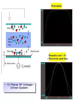
+. +. +. +. –. –. –. –. –. –. –. –. Potential. +. +. Sheath. +. +. Bulk Plasma. Sheath. Substrate. +. Density(cm^-3) : Electron and Ion. X direction. ~. 1D Planar RF Voltage-Driven System. Plasma Application Modeling, POSTECH. Klystron. 3 cm. 2 cm. Phase space.

Potential
E N D
Presentation Transcript
+ + + + – – – – – – – – Potential + + Sheath + + Bulk Plasma Sheath Substrate + Density(cm^-3) : Electron and Ion X direction ~ • 1D Planar RF Voltage-Driven System
Plasma Application Modeling, POSTECH Klystron 3 cm 2 cm Phase space Density uz Kinetic energy
PIC Overview • Applications of PIC model • Basic plasma physics: waves and instabilities • Magnetic fusion • Gaseous discharges • Electron and ion optics • Microwave-beam devices • Plasma-filled microwave-beam devices
Congratulations! It's nice to get emails like this, isn't it. Cheers, Mike Lieberman On Sep 28, 2005, at 5:46 PM, 이재구 wrote: > Subject: Your article has been downloaded 250 times! > Dear Professor Lee, > I am pleased to tell you that your article, "Particle and fluid > simulations of low-temperature plasma discharges: benchmarks and > kinetic effects", in Journal of Physics D: Applied Physics, Vol 38, > ppR283 (2005), has been downloaded 250 times so far. > > This was achieved in 12 days from the date of publication. To put > this into context, across all IOP journals 10% of articles were > accessed over 250 times this quarter. > You can link directly to your article at: > http://stacks.iop.org/0022-3727/38/R283> I would like to thank you for supporting Journal of Physics D: > Applied Physics and I trust that you have found our publication > process to be friendly and efficient. I hope you will consider > submitting further papers to the journal and encourage your > colleagues to do likewise. > Our publication times are highly competitive and we use a fully > electronic editorial process from submission to peer review to > production. Electronic submission to Institute of Physics journals > can be done very simply at the following web page: > http://www.iop.org/journals/authorsubs> We look forward to working with you again. If you have any queries > about the journal, please don't hesitate to contact me. > If you would prefer not to receive further updates on the number of > times this article has been downloaded, please reply to this email > with the word remove in the subject line. > Kind regards > Sarah Quin , Publisher > Journal of Physics D: Applied Physics > Institute of Physics Publishing > Dirac House, Temple Back, Bristol BS1 6BE, England
PIC Overview • PIC Codes Overview • PIC codes simulate plasma behavior of a large number of charges particles using a few representative “super particles”. • These type of codes solve the Newton-Lorentz equation of motion to move particles in conjunction with Maxwell’s equations (or a subset). • Boundary conditions are applied to the particles and the fields to solve the set of equations. • PIC codes are quite successful in simulating kinetic and nonlinear plasma phenomenon like ECR, stochastic heating, etc.
PIC-MCC Flow Chart • Particles in continuum space • Fields at discrete mesh locations in space • Coupling between particles and fields I II V IV III IV Fig: Flow chart for an explicit PIC-MCC scheme
I. Particle Equations of Motion • Newton-Lorentz equations of motion • In finite difference form, the leapfrog method Fig: Schematic leapfrog integration
I. Particle Equations of Motion • Second order accurate • Requires minimal storage • Requires few operations • Stable for
I. Particle Equations of Motion • Boris algorithm
I. Particle Equations of Motion Finally,
II. Particle Boundary • Absorption • Conductor : absorb charge, add to the global σ • Dielectric : deposit charge, weight q locally to mesh • Reflection • Physical reflection • Specular reflection • 1st order error • Thermionic Emission • Fowler-Nordheim Field Emission • Child’s Law Field Emission • Gauss’s Law Field Emission
II. Particle Boundary • Secondary electron emission + , – – • Photoemission • Ion impact secondary emission • Electron impact secondary emission • Important in processes related to high-power microwave sources
III. Electrostatic Field Model • Possion’s equation • Finite difference form in 1D planar geometry • Boundary condition : External circuit Fig: Schematic one-dimensional bounded plasma with external circuit
EECE695: Computer Simulation (2005) Particle-in-Cell Techniques HC Kim, SJ Kim,and JK Lee Plasma Application Modeling Group, POSTECH • References: • Minicourse by Dr. J. P. Verboncoeur (PTS Group of UC Berkeley) in IEEE International Conference on Plasma Science (2002) • “Plasma Physics via Computer Simulation” by C.K. Birdsall and A.B. Langdon (Adam Hilger, 1991)
XPDx1 Flow Chart I II V IV III IV Fig: Flow chart for an explicit PIC-MCC scheme
Collisions • Electron-neutral collisions • Elastic scattering (e + A → e + A) • Excitation (e + A → e + A*) • Ionization (e + A → e + A+ + e) • Ion-neutral collisions • Elastic scattering (A+ + A → A+ + A) • Charge exchange (A+ + A → A + A+)
V. Monte-Carlo Collision Model • The MCC model statistically describes the collision processes, using cross sections for each reaction of interest. • Probability of a collision event • For a pure Monte Carlo method, the timestep is chosen as the time interval between collisions. where 0< R< 1is a uniformly distributed random number. However, this method can only be applied when space charge and self-field effects can be neglected.
V. Monte-Carlo Collision Model • Computing the collision probability for each particle each timestep is computationally expensive. • → Null collision method 1. The fraction of particles undergoing a collision each time step is given by 2. The particles undergoing collisions are chosen at random from the particle list. 3. The type of collisions for each particle is determined by choosing a random number, Null collision Collision type 3 Collision type 2 Collision type 1 Fig: Summed collision frequencies for the null collision method.
Plasma Application Modeling POSTECH + + + + – – – – – – – – Capacitively Coupled Plasma – 1D PIC-MCC ~ j= 1, , N + + Sheath + + Bulk Plasma Sheath Substrate + • MCC (Monte-Carlo Collision)Processes • - Electron-Neutral Collisions • (Ionization, Scattering, Excitation) • - Ion-Neutral Collisions • (Charge-exchange, Scattering) ~ • 1D Asymmetric Dual-Freq. Voltage-Driven System
Capacitively Coupled Plasma – 1D PIC-MCC Vx vs. x for electrons Vx vs. x for ions Density vs. x Potential vs. x
Plasma Application Modeling POSTECH Ion Energy Distribution Function 20 mTorr 10 mTorr 50 mTorr 30 mTorr • High frequency : 100MHz (100V) • Low frequency :1MHz (102V) • Symmetric Discharge • L = 2.5 cm
Plasma Application Modeling POSTECH Electron Energy Distribution Function In the discharge center
Plasma Application Modeling POSTECH Comparison Between PIC and Experiment (II) Single langmuir probe measurement result from KAIST • Electron temperature is decreased as pressure is increased • Electron temperature is comparable to PIC simulation Table 1 Electron temperature from PIC simulation (pressure=110mT)
Plasma Application Modeling POSTECH • Low-energy electrons • : 2.40 eV (1.11e15 cm ) • High-energy electrons • : 1.00 eV (7.82e12 cm ) -3 -3 PIC-MCC versus Fluid Simulation (I) ~ 4eV Due to Ramsauer minimum • EEPF obtained from PIC/MCC is totally in disagreement with that of LFA because of nonlocal behavior of electrons.
IV. Coupling Fields to Particles • Particle and force weighting : connection between grid and particle quantities • Weighting of charge to grid • Weighting of fields to particles grid point a point charge
IV. Coupling Fields to Particles • Nearest grid point (NGP) weighting • fast, simple bc, noisy • Linear weighting • : particle-in-cell (PIC) or cloud-in-cell (CIC) • relatively fast, simple bc, less noisy • Higher order weighting schemes • slow, complicated bc, low noisy Quadratic spline NGP 1.0 Linear spline Cubic spline 0.5 0.0 Position (x) Fig: Density distribution function of a particle at for various weightings in 1D
IV. Coupling Fields to Particles Areas are assigned to grid points; i.e., area a to grid point A, b to B, etc Fig: Charge assignment for linear weighting in 2D
Plasma Application Modeling POSTECH Visible Light Sustain Electrode Sustain Electrode Bus Electrode Bus Electrode Front Glass Substrate MgO Discharge Dielectric layer Dielectric Layer Protection Layer Barrier Barrier Rib Address Electrode UV o 90 rotation Phosphor Rear Glass Substrate Phosphor(R,G,B) Address Electrode PDP Structure AC PDP Discharge in PDP
Plasma Application Modeling POSTECH 100Torr 200Torr 500Torr Striation Profiles in PDP – 2D PIC/MCC Anode Cathode • Pressure dependence of striations • : Number of peaks depend on the pressure and electrode size.
Input file(II) The direction 1.00 1.00, -1.00
Plasma Application Modeling, POSTECH The comparison of like-sign and opposite-sign results(I) Opposite-sign Like-sign • Like-sign : electron – electron two stream case • Opposite-sign : electron – ion two stream case
Plasma Application Modeling, POSTECH The comparison of like-sign and opposite-sign results(II) Field energy Kinetic energy • Field & Kinetic energy distribution in time is different. • The peak field energy value in like-sign case is higher than that of opposite- • sign case and the time to reach to the peak value longer than that of opposite- • sign case.
Plasma Application Modeling, POSTECH Simulation Domain of Klystron (SJ Kim) RF output port RF input port 9.55 cm 10.05 cm 13.07 cm E-beam 7.569 cm 6.66 cm Cylindrical Axis 37.2 cm • Simulation condition: • Beam emitter: I= 12 kA, ud =2.48e8 m/s • Input port : Rin=2300 , R=20 , f=7.69 GHz • Output port : R=47.124
Plasma Application Modeling, POSTECH Example of Klystron Simulation Phase space Density uz Kinetic energy
Plasma Application Modeling, POSTECH Simulation Results at 10 ns
Plasma Application Modeling, POSTECH Simulation Results at 6 us
Plasma Application Modeling, POSTECH KE as a Function of Beam Current
Plasma Application Modeling, POSTECH KE as a Function of Beam Energy
Plasma Application Modeling, POSTECH Klystron 3 cm 2 cm Phase space Density uz Kinetic energy
Plasma Application Modeling, POSTECH Simulation Results at 0.5 ns and 2.5 ns
Plasma Application Modeling, POSTECH Simulation Results at 10 ns and 20 ns
Plasma Application Modeling, POSTECH Simulation Results at 6 us
Plasma Application Modeling, POSTECH Simulation Results at 0.5 ns and 2.5 ns