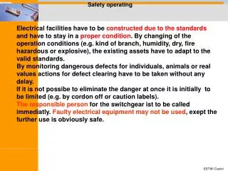
Safety operating
Safety operating. Electrical facilities have to be constructed due to the standards and have to stay in a proper condition . By changing of the operation conditions (e.g. kind of branch, humidity, dry, fire hazardous or explosive), the existing assets have to adapt to the valid standards.

Safety operating
E N D
Presentation Transcript
Safety operating Electrical facilities have to be constructed due to the standards and have to stay in a proper condition. By changing of the operation conditions (e.g. kind of branch, humidity, dry, fire hazardous or explosive), the existing assets have to adapt to the valid standards. By monitoring dangerous defects for individuals, animals or real values actions for defect clearing have to be taken without any delay. If it is not possibe to eliminate the danger at once it is initially to be limited (e.g. by cordon off or caution labels). The responsible person for the switchgear ist to be called immediatly. Faulty electrical equipment may not be used, exept the further use is obviously safe.
1. Before first starting up and after every change, repair or maintenance the asset is to be tested by an electrical technician. 2. Equipment/assets have to be re-tested in certain intervals. Emerging fault have to be diagnosed early enough in a certain time limit. The rule books must be respected by testing . By request a test log book with certain records is to be kept.
Air-insulated double busbar switchgear 10 kV Division into six compartments Switchgear with extractable switches (connect- and disconnect position) Switch truck out of panel for maintenance When circuit breaker ist solid buildt in, busbar and cable disconnectors are required
Details of a truck type switchgear Circuit breaker in test position Backout of circuit breaker on switch truck
Designs of switchgears in distribution substations Air insulated switchgears AIS • Insulation by air, • arcing control by air ore, sometimes, by vacuum Gas insulated switchgears GIS • sealed pressure system • Insulation by SF6, • Arcing control by SF6 oder vacuum • No refilling ofSF6 during lifetime • overpressure: 2 – 5 kPa (0,2 – 0,5 bar) • Quantity: approx. 2 kg SF6 in a ring-main-unit
Air insulated switchgear for distribution substations • type-tested switchgear (IEC 62271-200) • metal enclosed • Factory assembled (field-by-field) • Single compartment partition • assembly on baseframe • mind torques for assembly Dimensions for 10 kV: Width: 600 mm Length: 730 mm (CB-feeder: 900 mm) Height: 1900 mm Weight: 170 kg (CB-panel: 250 kg metering panel: 270 kg)
Gas-insulated switchgear for distribution substations • Compact transformer substations, • e. g. forwind power stations • Garage and vault substations • Underground and underfloor substations • Sidewalk substations • Damp, sandy or dusty areas Almost maintenance-free Welded switchgear vessel without seals, made of stainless Be carefull for drillings! Normally not expandable Dimensions: Scheme 10 up to 24 kV Width: 980 mm Length: 665 mm Height: 1400 mm Weight: 298 kg
Details Siemens 8 DJ 20Ready-for-service indicator Messdose magnet.Kopplung
Details Siemens 8 DJ 20voltage indicator energized faulty De-energized 3 4
Details Siemens 8 DJ 20operating mechanism 1 6 3 5 4 2
Overview of a distribution substation 4100 Safety guard Medium voltage switchgear AIS 2800 Substationaccessories A A LV and metering room meter Earthing terminal Duct bolt for earthing intrusion freer ventilation grille 4 cable entrances, Door with intrusion free ventilation grille Hauff HD 150
Overview of a distribution substation 2350 profile A - A
Overview of a distribution substation Scheme: 2 ring main feeder–1 transformer feeder
Overview of a distribution substation Operating control line Property line metering
Overview of a distribution customer substation Operation control line Metering panel Circuit breaker panel Customer disconnects Power utlity connects Property line
Designs of distribution substations Pole substation enclosured transformer towerstation
Designs of distribution substations Accessible substation with air insulated swichtgear Dimensions: 2,80 m x 3, 50 m
Designs of distribution substations MV switchgear air insulated Transformer with safety guard LV-switchgear Accessories
Maintenance of distribution substations Pre-condition: Station is disconnected, earthed and free for working Wartung: Switchgears: - clean contacts and lubricate with approved grease by manufacturer - de-lubricate breaker mechanism carefully and re-lubricate - Function check, check operating mechanism - check HRC-fuses (dirction of mounting, proper dimension, - check release with test fuse - check cable box - check position indication Transformer - clean, - check oil level NSpg.: - clean (Live working !), - Beschriftung kontrollieren Building: - clean ventilation grilles, - check roof, - clean indoor, - check outdoor, locks, - check signage - check earth resistance,
Maintenance policies n n n j j j criterion: importance Action required? criterion: Diagnosis CorrectiveMaintenanceCM ConditionBased MaintenanceCBM Time Based MaintenanceTBM ReliabilityBased MaintenanceRBM
Time Based Maintenance • maintenance in constant periods • exchange of assets after constant up-time • high availability • no use up to maximum expected life Most cost-intensive maintenance
Corrective Maintenance • Repair or replacement after failure • asset availability depends on equipment availability • no influence on time between failures Most competitivemaintenance
Condition Based Maintenance • Maintenance or repair depends on technical condition All identicalassetsaretreatedthe same way
Reliability Based Maintenance • Maintenance or repair depends on technical condition • significance of asset importance for network Best maintenancepolicy
Evaluation Process For a Significance Based Maintenance MV Switchgear LV Switchgear Transformer Building Terminal Box S Time SinceLast Visual Control Condition Of Substation
Evaluation Process For a Significance Based Maintenance: Condition Transformer Criterion 1 e.g. Condition of Tank Total Evaluation Of Component e.g. Transformer: x Points S Criterion n e.g. Energized Time
Evaluation Process For a Significance Based Maintenance: Condition 1. Asset Scaling: Score: 100: Bad Condition 0: Very Good Condition
Evaluation Process For a Significance Based Maintenance: Condition 2. Substation Normalized Condition of Transformer Substation: 29 (quite good)
Evaluation Process For a Significance Based Maintenance: Significance Total Index Normalized summation = 44,0
Kinds Of Criteria • identification of condition is necessary on-site • (Inspection) • Data from asset-Information system • (no changes during life-cycle of equipment • Data from Asset-Information System • (no changes during life-cycle of equipment) • Periodical estimation for equipment-groups • (spare part supply) K.O. - Criteria: activity normaly necessary at once ! Leakages, partial discharges etc.)
From Condition And Significance To Priority 100 Area 1 Condition Area 2 Area 3 Index g 100 Significance 36,5 Ranking of activity: The substation with the highest index is to be replaced first (area 1). The substation in the example above (area 3)gets an extended inspection period. In area 2 the substation will get a reduced inspectionperiod. By turning the angle of 45° you canchange the weighting between condition and significance
Limiting Values K.O.- criterium: maintenance when possible instantly, but not later than a year Single component bad: more than 30 pts (normalized) rehabilitation required against significance Total index: more than 60 pts (normalized) rehabilitation or maintenance to be proofed External initiation: civil works, conclusions from calculation
Inspections Periodical surveys: suggestion normalized period: 4 years if necessary (AIS with heavy contamination 2 years) Periodical maintenance: suggestion GIS: 10 years AIS with heavy contamination 4 years, depending on condition and special recommendations of manufacturer Special tools: thermography partial-discharge measures
Inspections Initial survey
Inspections Periodical survey
Cable distribution cabinet Thermography Bad connection in a MV cable sealing end - High investment cost - Education an training needs + Diagnostics of weak spots at an early stage + cost savings by specific improved efficiency damaged Diazed-element in a LV-switchgear
Measurement of partial discharge of a paper insulated MV-cable typ. max. PD-Values: paper insulated cable 10.000 pC XLPE cabele 7.000 pC
Live Maintenance • + operation without disconnection possible • no switching risk, no emergency generator required • + economic for refill of cable-boxes • Especially trained staff needed • A lot of technical equipment needed • - Residual risk
Inlet- and outlet-air h Pierce-proofed ventilation grille Increase of required area Ventilation grille for 10%Jalousie for 50% (free profile) Outlet-air ~ 1,1 x inlet-air PV = P0 + k x PK With k = 1,06 for oil filled tranformers and k = 1,2 für cast resin transformers