CP 208 Digital Electronics Class Lecture 7 March 11, 2009
530 likes | 797 Vues
CP 208 Digital Electronics Class Lecture 7 March 11, 2009. MOS Field-Effect Transistors (MOSFETs). 2. In This Class. We Will Continue to Discuss : Chap 4 MOS Field-Effect Transistors Following Topics: 4.2 Current-Voltage Characteristics 4.3 MOSFET Circuits at DC

CP 208 Digital Electronics Class Lecture 7 March 11, 2009
E N D
Presentation Transcript
MOS Field-Effect Transistors (MOSFETs) 2
In This Class We Will Continue to Discuss : Chap 4 MOS Field-Effect Transistors Following Topics: 4.2 Current-Voltage Characteristics 4.3 MOSFET Circuits at DC 4.4 MOSFET as an Amplifier & Switch 4.10 The CMOS Digital Logic Inverter BUT First: Home Work #2
Home Work No. 2 A logic inverter is implemented using the arrangement as shown in Figure above with switches having Ron= 1 kΩ, andVDD = 5 V. If vIrises instantaneously from 0 V to 5 V and assuming the switches operate instantaneously — that is, at t = 0, PU opens and PD closes — find an expression for vO(t) assuming that a capacitance C = 1 pF is connected between output node and ground. Find high-to-low propagation delay (tPHL). Repeat for vIfalling instantaneously from 5V to 0V. Again assume that PD opens and PU closes instantaneously. Find expression for vO(t) and hence find tPLH. If switching frequency of the inverter is 100 MHz what would be the Dynamic Power Dissipated.
Solution: At t=0 PU opens, V across Cap. cannot Change Instantaneously. at t=0+ the Output, vO(t0+) = 5 V. Cap. discharges thru Ron and Output Falls Exponentially to 0 V (ground). • vO(∞) = 0 V. Using the Output Eqn of STC Network for Step-function as I/P: y(t) = Y∞ - ( Y∞ - Y0+)e-t/τ vO(t) = vO(∞) – [v(∞)-vO(t0+) ]e-t/τ vO(t) = 0 – (0 – 5) e-t/τ vO(t) = 5 e-t/τ _____ (1)
τ = RC. To Find tPHL … when t= tPHL vO(t=tPHL) = 0.5(5+0) = 2.5 Eq (1) becomes: 2.5 = 5 e-tPHL /RC • e-tPHL /RC = 2.5/5 • etPHL /RC = 5/2.5 = 2 Taking ln on both sides: tPHL / RC = ln(2) tPHL = 0.69xRxC = 0.69x1000x10-12 = 0.69 n Sec
At t=0 PD opens, V across Cap. cannot Change Instantaneously. at t=0+ Output vO(t0+) = 0 V. Cap. Charges thru Ron and Output Rises Exponentially to 5 V (VDD ). • vO(∞) = 5 V. Using the Output Eqn of STC Network for Step-function as I/P: y(t) = Y∞ - ( Y∞ - Y0+)e-t/τ vO(t) = vO(∞) – [v(∞)-vO(t0+) ]e-t/τ vO(t) = 5 – (5 – 0) e-t/τ vO(t) = 5 – 5 e-t/τ _____ (2)
τ = RC. To Find tPLH … when t= tPLH vO(t=tPLH) = 0.5(0+5) = 2.5 Eq (2) becomes: 2.5 = 5 – 5e-tPLH /RC • 5 e-tPLH /RC = 5 - 2.5 • etPLH /RC = 5/2.5 = 2 Taking ln on both sides: tPHL / RC = ln(2) tPHL = 0.69xRxC = 0.69x1000x10-12 = 0.69 n Sec f = 100 MHz, VDD= 5 V C = 1x10-12 farads Pdynami = 100x106x52x 1x10-12 Pdynamic = 2.5 mW
About Mid-Term Exam … Will Include Following Topics: • Representation of Analog Signal by Binary • Digital Logic Inverters (General) • Propagation Delay and Power Dissipation • Diode Logic Gates • Propagation Delay • BJT as Amp and Switch (VTC) • BJT Digital Logic Inverter • Saturated vs non-saturated BJT • MOSFET Physical Structure and Operation • MOSFET as Switch • CMOS Digital Logic Inverter and VTC • Propagation Delay and Power Dissipation
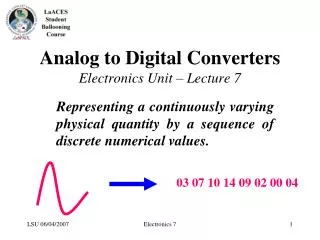
4.1.7 p-Channel MOSFET (PMOS) Fabricated on n-type substrate with p+ regions for D and S and p-channel is induced under gate Operates same way as n-channel device except vGS, Vt and vDS are negative Also, iD enters S and leaves D Because NMOS can be made smaller and operate faster and use lower supply voltage than PMOS, it has virtually replaced PMOS
4.1.8 Complementary MOS or CMOS: In CMOS the NMOS is implemented in p-type substrate and PMOS transistor is formed in a separate n-type region, known as an n well. Separated by thick oxide. Also, as alternate an n-type body is used and the n device is formed in a p well. Not shown are the connections made to the p-type body and to the n well; the latter functions as the body terminal for the p-channel device.
4.2 Current-Voltage Characteristics4.2.1 Circuit Symbol (a) Circuit symbol for the n-channel enhancement-type MOSFET. (b) Modified circuit symbol with an arrowhead on the source terminal to distinguish it from the drain and to indicate device polarity (i.e., n channel). (c) Simplified circuit symbol to be used when the source is connected to the body or when the effect of the body on device operation is unimportant
4.2.2 iD-vDS Characteristics Triode and Cutoff Regions are used as Switch and Saturation as Amplifier. Cutoff when vGS< Vt Triode when vGS≥ Vt (Channel Induced) and vGD> Vt (Channel Continuous) vGS - vDS > Vt {because vGD = vGS+ vSD = vGS-vDS} then vDS < vGS – Vt Saturation when vGD≤ Vt (Channel Pinched) vDS ≥ vGS – Vt
Triode: vGS≥ Vt (Channel Induced) vDS < vGS – Vt (Channel Continuous) In words: n-channel MOSFET operates in Triode Region when vGSgreater than Vt and Drain voltage is Lower than Gate voltage by at least Vt volts. Saturation: vGS≥ Vt (Channel Induced) vDS ≥ vGS – Vt (Channel Pinched) In words: n-channel MOSFET operates in Saturation Region when vGSgreater than Vt and Drain voltage does not fall below Gate voltage by more than Vt volts
(a) An n-channel enhancement-type MOSFET with vGS and vDS applied and with the normal directions of current flow indicated. (b) The iD–vDS characteristics for a device with k’n(W/L) = 1.0 mA/V2.
The iD–vGS characteristic for an enhancement-type NMOS transistor in saturation (Vt = 1 V, k’nW/L = 1.0 mA/V2).
Since the drain current is independent of drain voltage the Saturated MOSFET behaves as an ideal current source whose value is controlled by vGS. Large-signal Equivalent-circuit model of an n-channel MOSFET operating in the saturation region.
Relative Levels of terminal Voltages of NMOS Transistor for Operation in the Triode and Saturation Regions
Exercise 4.4 and 4.5 4.4 : NMOS transistor with Vt=0.7V has its source terminal grounded and a 1.5V dc applied to the gate. In what region does the device operate for (a) VD=+0.5 V? (b) VD=+0.9 V? (c) VD=+3 V? 4.5: If unCox=100 uA/V2, W=10 um, L=1um, find the value of drain current that results in each of the three cases, (a), (b), and (c) above.
4.2.4 p-Channel MOSFET Triode: vGS≤ Vt or vSG ≥ |Vt| (Channel Induced) vDS ≥ vGS – Vt (Channel Continuous) Saturation: vGS≤ Vt (Channel Induced) vDS ≤ vGS – Vt (Channel Pinched)
Relative Levels of terminal Voltages of PMOS Transistor for operation in the Triode and Saturation Regions
4.2.5 The Role of Substrate – Body Effect Usually S is Connected to B, which results in pn juction between substrate and channel (having a constant zero bias). In such case substrate/body does not play any role in ckt operation and it can be ignored.
4.2.5 The Role of Substrate – Body Effect In ICs substrate is common to many MOS transistors, and is connected to most negative power supply (positive for PMOS). The reverse bias voltage will widen the depletion region at Source and reduce the channel depth. To return channel to its former state vGS has to be increased. Increasing Reverse Substrate Bias Voltage, VSB results in increase in Vt as: 2Φfis typically 0.6 V and γ is fabrication-process parameter (or Body-effect Parameter). VBS gives rise to incremental change in Vt, which in turn results in change in iD even when vGS is kept constant. Thus, body voltage behaves as another Gate.
4.3 MOSFET Circuits at DC Example 4.2: Design the ckt of Fig so that transistor operates at ID = 0.4mA and VD = +0.5 V. Vt = 0.7, unCox = 100 uA/V2, L = 1 um, W=32 um
Solution: VD = 0.5 V and VG = 0V VD > VG NMOS operating in Saturation. Use saturation eqn of iD to find VGS: 400 = ½ x 100 x (32/1)x(VGS-Vt)2 (VGS-Vt) = 0.5 V VGS= 1.2 V Now VGS = VG+VS OR VS = VG-VGS VS = 0 -1.2 = - 1.2 V. RS = (VS-VSS)/ID = (-1.2 - (-2.5))/0.4 = 3.25 kΩ RD=(VDD-VD)/ID = (2.5 – 0.5)/0.4 = 5 k Ω
4.4 MOSFET as an Amp and Switch • MOSFET in Saturation Acts as a Voltage-Controlled Current Source • Changes in Gate-to-Source Voltage vGS gives rise to iD Where vDS = vGS -Vt
4.4.1 The Transfer Characteristic • Basic Circuit most commonly used for MOSFET Amplifier – Common Source or CS CKT • Because grounded Source Terminal is Common for both Input and Output • vGS = vI and controls iD • Output vO is obtained in RD vO = vDS = VDD – iDRD OR iD = VDD/RD – vDS/RD Assume vI to be 0 to VDD we analyze ckt to determine output vO that is VTC of CS Amplifier
4.4.3 Operation as a Switch • To use as Switch, the MOSFET is operated at the Extreme Points of the Transfer Curve • Device is OFF for vI < Vt and Operation is at Segment XA with vO = VDD • Device is ON when vI is close VDD and operation is close to point C with vO very small, vO = VOC at point C • Transfer Curve is similar to the form in Chap 1 for Digital Logic inverter • MOSFET CKT can be used as Logic Inverter with ‘Low’ voltage Level close to 0V and ‘Hi’ level close to VDD
4.10 The CMOS Digital Logic Inverter • The Basic CMOS Inverter • Utilizes two MATCHED enhancement type MOSFETS: QN (n-channel) and QP (p-channel) • Body of each is connected to Source
4.10.1 Circuit Operation Consider Two Extreme Cases vI = 0 (logic 0 level) and vI = VDD (logic 1 level). In both cases consider QN is driving and QP is Load (due to symmetry opposite will be identical)
Home Work No. 4 (Due April 01, 2009) Problems at the End Of Chapter 4. • Problem 4.108 • Problem 4.110 • Problem 4.112 • Problem 4.113
In Next Class We Will Continue to Discuss: Chap 4 MOS Field-Effect Transistors