Download
1 / 25
350 likes | 1.16k Vues
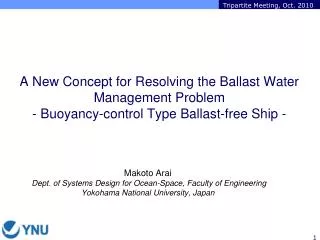
Refinement of the Ballast-Free Ship Concept. PI: Michael G. Parsons, Arthur F. Thurnau Professor Emeritus, NAME, University of Michigan Co-PI: Miltiadis Kotinis, Assistant Professor, MAE, Old Dominion University

E N D
Refinement of the Ballast-Free Ship Concept PI: Michael G. Parsons, Arthur F. Thurnau Professor Emeritus, NAME, University of Michigan Co-PI: Miltiadis Kotinis, Assistant Professor, MAE, Old Dominion University Project Goal: Clarify operational and economic issues related to the implementation of the Ballast-Free Ship concept
Traditional approach: Add ballast water to tanks to increase vessel weight in the light cargo condition Paradigm shift: Instead of adding weight, reduce buoyancy Ballast-Free Ship concept principles: Replace traditional ballast tanks with longitudinal, structural ballast trunks that extend beneath the cargo region below the ballast waterline. Connect trunks to the sea through a plenum at the bow and another at the stern. Trunks flooded in ballast condition. Pumped when finished. The natural hydrodynamic pressure differential between the bow and the stern region at speed induces a slow flow in the ballast trunks. Trunks are, therefore, always filled with “local seawater.” US Patent #6694908, 2004 The Ballast-Free Ship Concept
Comparison of Midship Sections greater depth to maintain grain capacity higher innerbottom to get ballast capacity below ballast waterline open lower floors to facilitate trunk cleaning three longitudinal trunks per side; each containing local water changed every 1½ hrs. Typical single-hull salty bulk carrier Ballast-free bulk carrier
Design Ballast-Free Seaway-sized bulk carrier Build a precision scale model for use in subsequent hydrodynamic tests (FY2006), Optimize the location and details of the plena openings, particularly aft, in order to, Reduce the large propulsion power penalty (+7.4%) found in earlier National Sea Grant study (FY2007) Confirm and better explain the large power decrease (-7.3%) observed in FY2007 (FY 2008) Goals of the Past GLMRI Effort
Seaway-sized Bulk Carrier Hull Form Design • Design based upon: Polsteam Isa design from Jiangnan LWL = 195.5 m LBP = 192.0 m B = 23.76 m D = 16.0 m TFL = 10.7 m Block CB = 0.835 Waterplane CWP = 0.909 Displacement = 42,546 t Ballasted to 40% fwd; 70% aft Speed in ballast = 15.5 knots Scale Ratio l = 37.92 (5 m model)
Five Meter (16.9’ LWL) Scale Model FY2006 Result
Intake and Discharge Locations – July ‘08 Tip of bulb for maximum input pressure STA17 – forward engine room bkhd STA19 – aft engine room bulkhead FY2007 and FY2008 Testing
Increased Resistance with Trunk Flow More consistent results STA17 +4.5% at 15.5 knots FY2008 Result
Effective Power (resistance)/hD = Delivered Power up 4.51% ? what really matters $$ Propulsive efficiency hD = hOhRhH = hPhH Open water propeller efficiency hO Relative rotative efficiency hR Hull efficiency hH = (1 - t)/(1 – w) hOhRhH Baseline hD = 0.487 x 1.0126 x 1.0876 = 0.536 STA 17 hD = 0.522 x 0.9593 x 1.1380 = 0.570 up down up +6.27% Required Power Comparison
Order of Magnitude Economic Comparison lowered fuel savings almost $1 per tonne grain (1%) cheaper to operate RFR = Required Freight Rate needed to make a profit annual cargo capacity 168,000 t grain
There is an increase in resistance (+4.5%) at STA17 There can be a decrease in required power (-1.6%) Ballast-Free Ship concept can result in significant savings compared to filtration and UV treatment etc. when ballast exchange is no longer allowed Still an issue of the effects of using stock propellers Conclusions from Testing in FY2008
Publications from GLMRI Effort Short Invited Articles Maritime Reporter Great Lakes/Seaway Review 2008 Yearbook of Maritime Technology (Scandinavia) Papers Kotinis, M. and Parsons, M. G., “Numerical Investigation of the Flow at the Stern of a Ballast-Free Bulk Carrier Model” 9th International Conference on Numerical Ship Hydrodynamics, Ann Arbor, MI, Aug. 5-8, 2007 Kotinis, M. and Parsons, M. G., “Hydrodynamic Investigation of the Ballast- Free Ship Concept” SNAME Annual Meeting, Ft. Lauderdale, Nov. 2007; in Transactions SNAME, 115, 2007. SNAME ABS/Captain Joseph H. Linnard Prize for the Best 2007 Paper Kotinis, M. and Parsons, M. G., “Hydrodynamics of the Ballast-Free Ship Revisited,” Great Lakes and Great Rivers Section Meeting of SNAME, Ann Arbor, MI, Nov. 13, 2008; to appear in Journal of Ship Production and Design
Propulsion Investigation using Optimal Propeller Design: Resolve issue of stock versus optimal propeller and further clarify expected power/fuel savings (- $$) Computational Fluid Dynamics (CFD), propeller design, rapid prototyping, MHL testing Details and Flow Resistance of Trunk Isolation Valves: Sluice gates Motor-operated butterfly valves Operations Capabilities of Trim/Draft Control Control is discrete (trunk segments full or empty) versus continuous (various levels in ballast tanks) Goals of FY2010 Project
Propulsion Investigation CFD analysis to obtain nominal wake in model scale Strength and cavitation requirements were also considered OpenProp software was utilized to obtain propeller optimal pitch and performance characteristics Propeller geometry was imported in Rhinoceros® to build a 3-D model Rapid prototyping is currently employed for the manufacturing of the propeller model FY2010 Project
Propulsion Investigation FY2010 Project
Propulsion Investigation FY2010 Project
Details and Flow Resistance of Trunk Isolation Valves: Early work used sluice valves – industry criticism New design with motor-operated butterfly valves corrugated bulkhead over motor operator bulkhead stool shell plating butterfly valve FY2010 Project
Details and Flow Resistance of Trunk Isolation Valves: Simulations using Gambit ® and Fluent ® Initial study (2004) results using sluice gates FY2010 Project
Capability to be Displayed with an Adaptation of Submarine Equilibrium Diagrams Weight or draft change • Draft change versus trim moment envelope Cases: • Discrete segments from ends only (full or empty) • Added piping ($$) to allow any discrete segment • Use piping to fill segments to any level Trim moment
Operations Capabilities of Trim/Draft Control Perform analysis using MaxSurf ® and HydroMax ® FY2010 Project
Thank You Questions?
Conventional bulk carrier FY2010 Project
Ballast-free bulk carrier FY2010 Project